How to Strengthen Electronic Cable Performance in Harsh Environments
What you'll learn:
- How environmental stressors degrade cable durability and electrical performance.
- How insulation materials and shielding architectures affect long-term reliability.
- Why engineers must balance tradeoffs when specifying cables for demanding operating conditions.

Why can’t the most common, commercial-off-the-shelf (COTS) cable be used in any environment?
Cables are often the last component considered during system designs. In many situations, they’re really the system’s lifeline — if a cable goes down, the entire system can stop. For example, if the cable system used for data transmission in an automotive environment or in a spacecraft fails, the communication between the craft and mission control could be lost.
Cable reliability is based on both durability and signal integrity. The ideal cable system should be engineered to last the life of the product in any environment.
The environments that cable systems find themselves in today are becoming more challenging. A harsh environment is one in which a cable’s reliability, signal integrity, and life expectancy can be compromised. In essence, a harsh environment is where a standard or common commercial cable will not perform in that specified environment.
For example, cables are being exposed to extreme temperatures, chemicals, abrasion, and electrical noise. Additional factors can include the need for resisting, flammability, smaller diameters, and lighter materials for cable systems that last longer and cost less over the life of the system. Informed material and design choices can deliver dramatic performance to address conditions within harsh environments.
Defining Harsh Environments
Ground vehicles, space, aircraft, maritime, and industrial uses each have unique challenges and needs. For example, a maritime environment will emphasize low smoke and zero halogen materials, physical toughness, and chemical compatibility without regard to size and weight. Figure 1 outlines some of the rigors of specific applications and/or harsh environments with emphasis on the most critical stressors.

In all cases, designing for these harsh environments is ultimately a tradeoff: The demanding mechanical durability required in aerospace can be met with correct material thickness and type, but must be done so with attention to added size and weight.
The following paragraphs will detail these stresses that create the challenges for designing electrical cables for harsh environments.
Selecting Materials for Extreme Temperatures
Temperatures in harsh environments can range from as low as −200°C in space environments to upwards of 260°C, while some applications go as far as to mandate surviving direct flame for short periods of time.
Common commercial cables are inadequate at either end of this temperature spectrum: materials like polyvinylchloride (PVC), polyurethane (PU), and polyethylene (PE) become far too brittle at sub-ambient temperatures, which causes premature failure via fractures and cracking. When exposed to temperatures in excess of 80°C, these cheaper insulation options lead to short circuits, jacket adherence, and in cases above 100°C, complete melting.
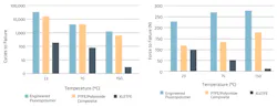
Selection of insulation such as fluorinated polymers (FEP, PFA, XLETFE, PTFE) or polyimides allow for continuous use up to 200°C. Although these polymers don’t chemically break down at these temperatures, the specific requirements of the insulation at elevated temperature must be considered. Typical use temperatures for these insulation materials are summarized in Figure 2.
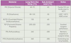
While some polymers are good candidates for a 200°C application and can be used without obvious failures such as melting or noticeable physical changes, performance criteria at the given temperature must be considered when designing an electrical cable. An example is the use of high-speed data cables in aerospace (or similar high temperature environments.
Figure 3 shows two aerospace grade Cat6A cables. Cable A is an expanded/foamed FEP dielectric; Cable B is a PTFE dielectric.
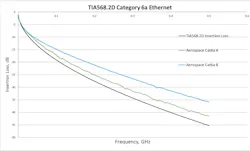
Both cables are adequately designed to perform in ambient conditions. However, when the performance is evaluated at the upper end of the allowable use temperature of 200°C, loss increases in one of the data cables, pushing it beyond the allowed specification limit (Fig. 4).
Ultimately, in this case, physics can’t be ignored — as temperature increases, copper’s resistance increases linearly and will impact loss. While the physics of the material can’t be changed, a solid understanding of the environment, as well as making good material and design choices, can minimize the inherent losses due to high temperatures.
In the above case, the better design choices (PTFE dielectric and improved processing techniques) lead to the cable having superior ambient performance and a less severe reduction at temperature. It results in a cable that continues to provide performance at this extreme temperature.
>>Download the PDF of this article, and check out the TechXchange for similary themed articles and videos
Other important considerations for extreme temperature are adequate conductor plating and choice of metal for conductor. Plating such as tin, which is commonly used in more common commercial cables, will oxidize and form copper-tin compounds. This will lead to loss of solderability and reduction in performance (larger voltage drops and loss).
Toxicity and Flammability in Extreme Environments
At the most extreme cases, cables within many industries, such as aerospace, industrial, and especially maritime, must be selected to prevent the endangerment of life or the propagation of flame.
In these industries, standard committees such as Federal Aviation Administration (FAA), Society of Automotive Engineers (SAE), Association Connecting Electronics Industries (IPC), and National Electrical Manufacturers Association (NEMA) outline strict requirements for the toxic gas emissions, in confined spaces, of potentially life-threatening compounds such as CO, HF, HCL, and others.
Standard common commercial cables typically are made of PE or PVC due to ease of processing. They provide adequate performance for mild environments. Considering these two materials for toxicity and flammability, though, both have their limitations.
PE can ignite and cause significant system-level problems in this extreme case, while PVC has shown to emit dangerous chemicals like HCL during flaming conditions (Fig. 5). In the case of fluoropolymers, although harmful chemicals are emitted, the concentrations from combustion tend to be tolerable amounts as shown by FAA testing.
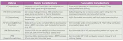
When cable insulations are selected that are capable of igniting, such as polyethylene, it can lead to a domino effect of increasing the severity of a fire event. Insulations such as PVC, which unlike PE are self-extinguishing, will still burn and expel molten droplets that further spread the risk of a catastrophic event.
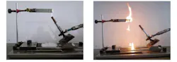
Figure 6 shows an example of a horizontal burn test, which is used to determine the flammability rating for materials in harsh environments. In this case, the material can spread via incendiary droplets, which can lead to additional ignition and uncontrolled fire.
One notable case study where cable design choices led to a catastrophic event is the Browns Ferry Nuclear Plant.
Cables within the nuclear plant weren’t adequately assessed for flammability. A fire that ideally would have been localized, ignited insulation on polyurethane cabling and seals, allowing the fire to spread through bulkheads. It resulted in over 600 burned cables.
This brought to bear over 10 million dollars of direct cost for replacement and repair, and loss of over 200 million dollars from the power plant being inoperable for an extensive period of time. In addition to the direct impact of the propagation of the fire, additional systems that were meant to limit the fire, such as fire suppression or warning systems, were inoperable due to the inadequacy of the cabling selected.
Though perhaps not important for all applications, in harsh environments, it’s typically expected that in such situations, the selected cable will not propagate flame or endanger the end user via toxic exposure, making an already dangerous situation worse.
Chemical Exposure in Harsh Environments
Cable insulations within harsh environments often must withstand varying degrees of chemical exposure. With typical common commercial cable, low-cost options can be suitable for some environmental exposures, but they fail to protect against aggressive cleaning agents or oils/fuels.
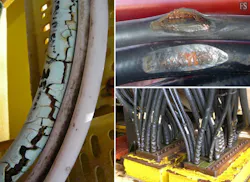
Polyethylene offers good resistance to moisture and many common chemicals. However, it can degrade under prolonged exposure to strong oxidizing agents or concentrated acids. PVC provides fair chemical resistance, but it’s vulnerable to solvents, oils, and certain hydrocarbons, making it less suitable for harsh industrial environments without protective additives. In cases of chemical exposure, PVC jackets can swell or crack, leading to reduced life or in severe cases, immediate failure (Fig. 7).
PTFE, on the other hand, is virtually impervious to chemical attack. It maintains stability against acids, bases, solvents, lubricants, and corrosive agents even at extreme temperatures. Thus, PTFE is the preferred choice for highly aggressive chemical environments.
Mechanical Stressors and Cabling
Cables in demanding environments face multiple mechanical challenges that can compromise their structural integrity and electrical performance. These stresses include tensile forces, compression, abrasion, flexural fatigue, and impact shocks, often combined with thermal cycling and vibration. Such events can reduce lifetime of the cable, impacting cost, or in worse scenarios, result in complete system failure.
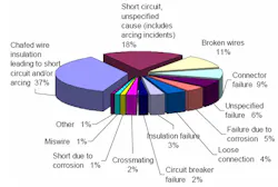
Within aircraft, abrasion from chafing against aircraft structures, devices, or other wires causes failures to cables in Electrical Wiring Interconnection Systems (EWIS). A study conducted by the U.S. Navy revealed this number to be as high as 37% of aircraft wire failures (Fig. 8).
Durability is critical when addressing mechanical factors, and it’s mainly a function of material choices and design. Of the materials previously discussed, only a few can bring appreciable protection against mechanical degradation.
For industrial environments, PE, typically used in common commercial cables, can bring decent performance for machinery and building controls. However, for transportation, the additional factors of flame resistance and toxicity preclude its use.
In maritime and rail environments, a cable design can increase wall thicknesses, leading to potential abrasion. Increased wall thickness comes with increased rigidity, which makes routing the cables a challenge (discussed in more detail below). In addition to routability, for rolling vehicles and aerospace, the added material thickness (weight) comes at a heavy price.
New materials are always being investigated to bring performance advantages with fewer tradeoffs. That’s where fluoropolymers can really help.
While PTFE typically isn’t considered a good option for abrasion resistance, new forms of PTFE called “engineered fluoropolymers” have profoundly higher mechanical strength. On cables, this vastly improves mechanical durability without additional weight (Fig. 9).
Routing cables can be a challenge in all industries. Getting the wires in place often can damage them in the process. That’s why cable flexibility is important, especially in harsh environments.
Space is typically constrained in applications such as industrial and vehicles/aerospace, which leads to cable bundling. In cases of bundling, starting with a less flexible cable is magnified by the number of cables being routed together. With large-gauge, high-power cables, if the cable is too rigid, the attachment to connectors presents real limits in terms of retention force.
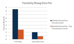
Figure 10 shows a design choice that can significantly affect the flexibility (force to bend) of a cable, specifically highlighting the impact of the outer jacket. Engineered fluoropolymer is inherently less stiff than extruded plastics such as FEP. Furthermore, the increased material strength allows the jacket to be thinner while maintaining all of the other properties required in harsh environments. In this case, the engineered fluoropolymer jacket adds roughly 2 Newtons of force during bending, while the thicker, extruded FEP jacket adds almost 6.5 Newtons.
Electrical Integrity and Rugged Cabling
Regardless of environment, electrical integrity, whether low-voltage signaling or high-voltage, high-amperage power cabling, is the ultimate purpose of an electrical cable. Take, for instance, a data cable. While a selected design may work great in a lab environment, systems where these cables are installed have significantly different needs. In this case, the harsh environment can be considered “electrically harsh,” experiencing major external electromagnetic interference (EMI) with the desired signal that results in lost data or slow performance (auto-negotiation).
Once again, considering typical off-the-shelf cables, many electronic cables, e.g., Ethernet, look to minimize expensive components such as silver-plated copper conductors and braid, as well as time-consuming process steps like individually shielding the data cable pairs. While this can work in low-EMI environments, electrically harsh environments such as aircraft, automated industrial applications, and defense land vehicles require a better solution.
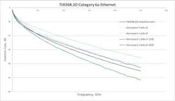
Figure 11 shows the shielding effectiveness of two cables used in aerospace applications. This test monitors the signal coupling between an external source and the cable under test; a lower value (more negative) shows that the cable is better protected from external electrical noise. The blue line has a foil shield on the pairs and a braid over all pairs, whereas the green shows a cable with a single braided shield overall.
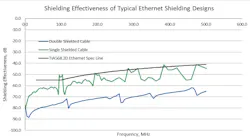
This design choice results in a difference of around −20 dB at 500 MHz. In terms of voltage, this −20 dB represents roughly a 10X difference! By going this route, it turns out the blue cable is actually lighter than the green cable.
Conclusion
Designing electronic cables for harsh environments is a multidisciplinary challenge that demands more than simply upgrading materials. It requires a holistic approach — understanding environmental stressors; balancing tradeoffs between weight, flexibility, and durability; and meeting stringent safety and performance standards. Advanced polymers, engineered fluoropolymers, and optimized shielding strategies enable cables to withstand extremes of temperature, chemical exposure, mechanical wear, and electromagnetic interference without compromising reliability.
Ultimately, success lies in integrating robust design practices with rigorous testing and lifecycle cost analysis, ensuring that cable systems remain the dependable lifeline of critical applications — from aerospace and maritime to industrial automation — throughout their operational life.
>>Download the PDF of this article, and check out the TechXchange for similary themed articles and videos
About the Author
Benjamin Lavallee
New Product Development Engineer, W. L. Gore & Associates Inc.
Benjamin Lavallee is a Product Development Engineer at W. L. Gore & Associates. His expertise lies in materials science and process engineering, with a focus on product development and analysis.
Grant Lawton
Applications Engineer, W.L. Gore & Associates Inc.
Grant Lawton is an Applications Engineer at W.L. Gore & Associates Inc. He has a demonstrated history of working in the aerospace industry.
Comment About the Article
To join the conversation, and become an exclusive member of Electronic Design, create an account today!

Leaders relevant to this article: