Filtering Out EMI in Rugged Aerospace and Defense Systems
What you'll learn:
- How more compact system designs and harsher operating conditions are increasing EMI risks in the aerospace and defense sectors.
- How to select EMI-filter connectors, with practical guidance on interpreting datasheets and balancing the tradeoffs between different form factors.
- How placement, grounding, and other decisions related to system integration directly impact EMI performance and system reliability.

In the design of mission-critical aerospace and defense systems, few issues are as disruptive as the late-stage discovery of electromagnetic interference (EMI). A system that performs perfectly on the bench can fail catastrophically during final compliance testing, triggering costly redesigns that in turn can cause budget overruns and critical project delays. When a platform fails to meet its mission requirements because of an unforeseen EMI issue, the consequences extend far beyond the engineering lab.
This challenge is intensifying, driven by two powerful and conflicting industry trends. The first is the proliferation of high-EMI sources within modern platforms, such as switch-mode power supplies, high-speed data lines, and powerful transmitters. The second is the relentless push for miniaturization, where the mandate to optimize size, weight, power, and cost (SWaP-C) forces engineers to package sensitive electronics into smaller, physically demanding enclosures.
Historically, EMI mitigation was a two-part strategy, relying on smart board-level design and comprehensive shielding to prevent interference, with targeted filtering addressing any remaining noise. As electrical and physical densities increase, however, traditional shielding alone is often insufficient to guarantee signal integrity. Integrated filtering has now become an essential component of modern aerospace and defense design.
The engineering challenge is to select and integrate an interconnect that treats signal integrity and physical durability as a single, unified entity. So, it helps to have a step-by-step guide to EMI filtering in ruggedized systems.
Fundamentals of EMI Filters: What They Do and How They Do It
An integrated EMI filter connector uses specialized low-pass filter technology, not conventional shielding. This approach uses custom coaxial components built directly into the connector's contacts to disrupt and divert unwanted radio-frequency (RF) signals at the precise point of interconnection, preventing them from both entering and exiting a shielded enclosure to contaminate a system.
At its core, the filtering mechanism functions as a specialized low-pass filter. These filters act as frequency-selective gatekeepers, allowing desired low-frequency signals or DC power to pass while blocking high-frequency noise. The critical parameter is cutoff frequency, where the filter begins to attenuate the signal. Unwanted high-frequency energy is shunted through a low-impedance path to ground and safely dissipated as a minute amount of heat.
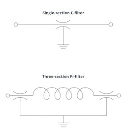
Engineers typically select from two common low-pass configurations. A C-filter provides a cost-effective, single-section filtering for general-purpose applications. The insertion loss slope for these filters is ~20 dB per decade.
For more severe EMI environments, a Pi-filter offers more aggressive, three-section attenuation. By incorporating an inductive element between two capacitive elements, the Pi-filter creates a significantly steeper attenuation curve for more demanding applications (Fig. 1). The slope of three-section filters is ~60 dB per decade.
Beyond the required attenuation level, engineers must also consider the system's source and load impedance. A deliberate mismatch between filter and system is key to maximizing noise rejection.
As a general rule, a capacitive filter element should face a high-impedance line, while an inductive element should face a low-impedance line. Because both C-filters and Pi-filters are capacitive at their inputs and outputs, they’re most effective in systems with high source and load impedances.
Coaxial ceramic capacitors enable the high-frequency performance of these filters. They offer a distinct advantage over standard, board-level multi-layer chip capacitors (MLCCs). MLCCs perform poorly in the ~100 MHz and higher range common to modern RF systems due to their own parasitic inductance and self-resonance. The coaxial structure of the capacitors in filtered connectors is designed specifically for high-frequency performance by minimizing parasitic equivalent-series inductance and resistance (ESL and ESR) of the component.
A vertically integrated capacitor manufacturing process makes it possible to package the EMI filter within a standard connector footprint, creating a drop-in replacement for an unfiltered connector that requires no changes to the system's mechanical design. For engineers working under strict SWaP-C constraints, adding robust EMI protection without a size or weight penalty is a significant design advantage.
A Step-by-Step Guide to Selecting EMI Filter Components
In aerospace and defense applications, component selection is a far more rigorous process than in typical commercial design. The decision for these high-reliability connectors is guided by stringent reliability standards and the ability to survive extreme environmental factors.
>>Download the PDF of this article, and check out the TechXchange for similarly themed articles and videos


Compliance with standards such as MIL-STD-202 and MIL-STD-810 for durability and MIL-STD-461 and DO-160 for lightning transient survival is often a baseline requirement, setting a high bar for performance in environments characterized by high shock and vibration. The selection process can be broken down into four steps.
Step 1: Define Electrical and Physical Requirements
A successful selection process begins with a holistic definition of the application's requirements. The initial step must account for electrical demands and the physical realities of the operating environment.
Electrical requirements span from fundamental voltage and current ratings to the ability to withstand specific transients. Physical requirements are just as important, defining the component's need to resist corrosion and maintain a proper seal against moisture, all while operating reliably under significant thermal loads.
Step 2: Conduct a Thorough Datasheet Analysis
With these comprehensive requirements defined, engineers can effectively analyze a component's datasheet. A robust analysis involves examining the entire attenuation curve to understand the filter's performance across a broad frequency spectrum, rather than focusing on a single insertion loss value. These filtering specifications must be evaluated alongside the component's voltage and current ratings to accurately predict real-world performance under operational electrical stress.
Step 3: Consider Location and Durability
Balancing physical durability with the component's footprint is the next step. The component’s physical location within the system dictates its required level of ruggedness. A connector housed in a protected, benign internal environment has vastly different durability requirements than one exposed to external operational conditions on an airframe or vehicle.
Step 4: Choose the Optimal Form Factor
The location analysis directly informs the choice of form factor. Options range from compact filter plates, ideal for high-density filtering in benign internal environments, to rugged D-Sub connectors that serve a wide range of demanding applications.
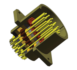
For the most extreme conditions, premium circular connectors provide the highest degree of protection. Their durable mechanical shells and sealed interfaces are engineered to withstand the combination of severe shock, vibration, and corrosive exposure common to external military and aerospace applications (Fig. 2).
Best Practices for Integrating EMI-Filtered Connectors
Selecting the right filtered connector is only part of the solution. The component's real-world performance depends on its physical integration into the larger system. Even the most advanced filters are rendered ineffective by poor implementation.
Mechanical choices, especially those for placement and grounding, directly influence the connector's ability to mitigate EMI and are as critical as its electrical specifications.
Prioritize Placement at the I/O Wall
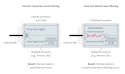
An effective filtered connector must be mounted directly on the wall of the shielded enclosure at the input/output (I/O) point. This placement provides a distinct architectural advantage over board-level filtering.
When a filter is placed on a printed circuit board (PCB) inside an enclosure, the noisy signal travels along a cable from the I/O wall to the board. During this transit, the cable itself can function as an antenna, radiating high-frequency noise within the enclosure before the signal reaches the filter (Fig. 3).
Establish a Low-Impedance Ground Path
The ground path forms the mechanical-to-electrical interface. The filter's function is to divert unwanted high-frequency energy to the system's ground. It can only do so with a clean, direct connection to the shielded enclosure.
Common and seemingly minor mistakes will severely degrade or even negate the filter's performance. Mounting a connector to a painted or anodized surface without removing the non-conductive finish, for example, creates a high-impedance path that prevents the filter from working. Using a non-conductive gasket between the connector and enclosure wall has the same detrimental effect.
A reliable, low-impedance ground path depends on savvy choices made during mechanical design and assembly. This includes choosing a conductive surface finish or careful surface preparation, such as masking the connector mounting area before painting or using a spot-facing tool to remove the non-conductive layer after finishing.
A conductive elastomer gasket is essential for maintaining a continuous shield. And mounting hardware, including screws and lock washers, must create a solid metal-to-metal connection that will not loosen under vibration.
These mechanical details are what preserve the integrity of the ground path over the system's entire operational life.
Maintain a Completely Sealed System
Finally, the filtered connector must be treated as one component of a complete, sealed system. EMI will always follow the path of least impedance, and any gap in the shielding creates an opportunity for noise to bypass the filter entirely. A small, unsealed seam or a hole drilled for a cable can act as a slot antenna, unintentionally channeling external noise directly into the enclosure and compromising sensitive electronics.
A proactive EMI strategy requires a holistic view, where the integrity of the overall shielded environment matches the integrity of the filtered connector.
Integrating EMI Filtering Early to Improve System-Level Performance
The challenges of EMI now are inseparable from a system's mechanical and thermal stresses, creating a complex problem that can’t be solved in isolation or as an afterthought. A reactive approach that treats filtering as a late stage fix often leads to project delays and costly redesigns. Today’s aerospace and defense design environment requires a fundamental shift in process, moving from late-stage problem-solving toward proactive, early-stage engagement.
Pivoting to this model involves addressing filtering and shielding requirements at the beginning of the design cycle, a phase often guided by mechanical engineers responsible for system packaging. When EMI mitigation is treated as a core requirement alongside mechanical and thermal constraints, the engineering team can make more informed decisions about everything from system layout and component placement to overall interconnect strategy. Proactive planning helps avoid cumbersome and expensive fixes later.
The industry's relentless push toward miniaturization and higher-frequency performance reinforces the need for this approach. As design margins shrink and systems become more electronically dense, the opportunities for late-stage fixes become increasingly limited.
A problem that might have been solved with a simple shield in a previous generation of technology may now require a complete board-level redesign. Early engagement is the most effective way to mitigate this risk.
Collaboration with an experienced component supplier provides the deep technical expertise required to develop effective aerospace EMI solutions, along with a versatile component portfolio to match the application's specific needs. This expertise often is rooted in capabilities, such as the vertical integration of critical component manufacturing for the custom ceramic capacitors that form the filter’s core.
A broad range of available components, from rugged D-Sub and circular connectors to EMI filter plates and RF terminations, gives engineers flexibility to implement a take-charge design strategy for high-stakes applications. Crucially, this portfolio also provides solutions for the inevitable last-minute discoveries, where a drop-in filtered connector can solve an EMI issue without requiring a costly mechanical redesign.
A proactive, system-level approach elevates the interconnect beyond a simple component. It becomes a vital subsystem that actively protects RF signal integrity, enhances physical durability, and contributes directly to overall mission reliability.
>>Download the PDF of this article, and check out the TechXchange for similarly themed articles and videos
About the Author
Alicia Truax
Product Manager, RF and Microwave Products, Molex
Alicia Truax is Product Manager for RF and Microwave Products at Molex. Alicia holds a Bachelor's degree in Business from Southern New Hampshire University.
Comment About the Article
To join the conversation, and become an exclusive member of Electronic Design, create an account today!

Leaders relevant to this article: