This file type includes high resolution graphics and schematics when applicable.
Light-emitting diodes (LEDs) are semiconductor devices that emit light when an electrical current passes through semiconductor materials. But for LEDs to perform at their best they need the assistance of LED drivers to provide better efficiency, reliability, and longevity.
LED drivers are electrical devices that prevent damage to LEDs by regulating the forward voltage (VF) of the LED that changes with temperature, avoiding thermal runaway while delivering a constant current to the LED. LED drivers also aid efforts to meet new energy requirements (e.g., Energy Star).
The steady growth of LED lighting technology has generated a wide range of LED-driver IC options in the semiconductor market. An appropriate driver generates a successful application. Some of the major developments in LED applications that have occurred and continue to evolve are as follows: dimming LED lamps, automotive lighting, LED signage, smartphone backlighting, and TV backlighting.
Here we present five different LED driver products for the major developments in LED applications mentioned earlier:
1. Dimming of small-form-factor lamps.
Few LED applications use the ON and OFF setting, as dimming helps to reduce energy consumption. There are two popular methods for dimming LEDs in switch-mode driver circuits: analog and Pulse-Width Modulation (PWM) dimming.
Analog Dimming refers to the adjustment of the nominal LED current. The analog voltage is adjusted and the LED current is changed to achieve dimming. This approach is not acceptable in many applications because there is a color shift with current variation. In contrast, pulse width modulation (PWM) dimming is accomplished by adjusting the nominal LED current by switching ON and OFF at a sufficiently high frequency to avoid a flickering effect.
One of the challenges of dimming is pairing LED lights with TRIAC or phase-cut dimmers that were never designed for LEDs. However, an array of products exist that can be used in this application. For example, Power Integrations offers the LYTSwitch-7 (Fig. 1). This buck LED driver IC has a buck topology with a power factor higher than 0.9. It is compatible with TRIAC dimmers capable of delivering up to 22 watts. The 735V integrated MOSFET ensures sufficient overvoltage protection during line surge occurrence. Its design offers a wide input (90 VAC – 308 VAC) and output voltage range operation. An EMI pi filter blocks differential and common mode noise. Bleeders are not included in the design; passive damping and a single winding inductor are used for TRIAC management.
2. Automotive lighting.
The LED automotive lighting market is actively growing. Every automotive lighting solution includes a distinctive LED driver; they are used for energy saving solutions, visibility, etc. Depending on the application, sometimes it’s better to use linear drivers instead of switching drivers. This also applies to automotive lighting if the LED lights are outdoors or indoors or on the back or on the front of the car. They will dissipate heat at different levels, depending on the environment and placement.
LED lighting can improve the safety of drivers and pedestrians by enhancing the range of visibility when the headlights are turned ON, OFF, or dimmed to efficiently perform at any stage of the journey. LED headlights present several challenges because the input voltage can vary depending on the condition. Therefore, step down (buck) and step up (boost) topologies are demanded for better performance.
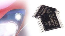
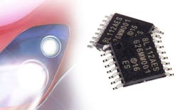
The S6BL112A (Fig. 2) single-output synchronous Buck LED driver from Cypress, for example, supports both analog and PWM dimming functions. It includes a frequency adjust pin that allows the user to adjust the frequency from 205 kHz to 2.1 MHz. The switching frequency (FOSC) is programmed by using an external resistor (RRT) connected between RT and GND.
Cypress’ S6BL112A Automotive LED driver features an input voltage range of 4.5-42 V that allows it to handle extreme operating conditions such as cold-cranking. Cold cranking occurs when the automobile engine starter draws an excessive amount of current due to starting the engine in cold temperatures. It also can function during load dump, which is a power surge that occurs when an automobile battery is disconnected while the alternator is supplying current during engine operation.
3. 16 × 16 LED displays.
16 × 16 displays are becoming more common, as they are great for outdoor use like storage signs, billboards, public transport signs, etc. Most of LED displays today are 8 × 8 and cannot communicate many international alpha-numeric characters. With a 16 × 16 display, however, it is possible to create signs in multiple languages that require more LEDs.
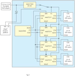
Recently, Maxim released a reference design (MAXREFDES99#) (Fig. 3) that integrates four of its MAX7219 LED drivers to create a 16 × 16 display with 256 LEDs. The MAXREFDES99# can be powered from a wall-wart which provides a minimum of 7W of power and an output voltage in the range of 7.5 V dc to 12 V dc. The reference design works with both Arduino and ARM mbed platforms.
The MAX7219 is a compact, serial input/output common-cathode display driver that interfaces microprocessors (µPs) to seven-segment numeric LED displays of up to eight digits, bar-graph displays, or 64 individual LEDs. Here is a short video of the display in action that I took while visiting Maxim’s demo room in San Jose.
4. Smartphone backlighting.
LEDs enable thinner backlight designs and support advanced backlight architectures that reduce PCB area and lower cost. The amount of LEDs changes depending on the size of the smartphone display. Bigger displays require more LEDs for backlighting applications.
Inductive drivers (inductive DC-DC converters) are very efficient when driving applications with multiple strings of LEDs. Because they operate more efficiently than single strings of LEDS at lower output voltages, they result in longer battery run-time.
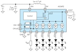
AMS' AS3492 (Fig. 4) is an inductive DC-DC converter that can drive up to five strings with two LEDs each in series with a system efficiency of 86% (DC-DC and current sources combined). The DC-DC converter operates at a fixed frequency of 2 MHz and includes soft startup to allow easy integration into noise-sensitive RF systems.
The output of the DC-DC converter is used for five current sources connected to up to 10 LEDs. The AS3496 has the following built-in protection mechanisms: Short LED protection (SLP), Open LED Protection (OLP) and Over Voltage Protection (OVP). This display backlight driver has been designed specifically for mobile phones, digital cameras, PND and PMPs.
5. TV backlighting.
LEDs have been replacing cold cathode fluorescent lamps (CCFLs) and Liquid Crystal Displays (LCDs) for backlight technology in many sizes of TVs, monitors, laptops, etc.
The backlight unit (BLU) in a TV or monitor is a major source of power consumption. LED drivers can offer significant power reduction through different backlight architectures: direct and edge backlight. In the edge backlight architecture, the LEDs surround the edge of the display. This approach offers the advantage of cost reduction by using fewer LEDs. For its part, direct backlight architecture puts the LEDs directly behind the display. In doing so, it provides better contrast but at a higher cost.
Two major dimming modes are used for LED backlight applications: global dimming (all LED strings are dimmed together) and local dimming (LED strings are dimmed independently).
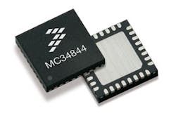
Among the products targeting this market is NXP Semiconductor’s MC34844 (Fig. 5), an LED driver for backlighting small- and medium-size LCD panels. It specifically serves low-power portable and high-definition devices (e.g., monitors and HDTV to 42 in., personal computer notebooks, GPS screens, small-screen televisions, etc.). Operating from supplies of 7 to 28 V, the MC34844 is capable of driving up to 160 LEDs in 10 parallel strings. The integrated boost converter generates the minimum output voltage required to keep all LEDs illuminated with the selected current, providing 90% efficiency (dc-dc). The MC34844 also includes a Pulse Width Modulation (PWM) generator for LED dimming. The LEDs can be dimmed to one of 256 levels, programmed through the I2C/SM-bus interface. Therefore dimming ratios up to 65,000:1 (256:1 PWM, 256:1 Current DAC) can be supported. External PWM inputs may also be used.
The MC34844 features LED over temperature protection, LED short protection, and LED open-circuit protection. The IC includes overvoltage protection, overcurrent protection, and undervoltage lockout. To achieve enough voltage to drive a number of LEDs in series, a boost converter is implemented to produce a higher voltage from a smaller one, which is typically used by the logical blocks to do their function.
There are many approaches for controlling LED lighting; every application is different, and LED drivers can provide efficiency and reliability by selecting the appropriate parameters. As technology advances we will see better LED driver applications capable of minimizing power consumption without trading-off in terms of efficiency, switching frequency, component counts, etc. We will see more LED drivers and sensors working together within the Internet of Things (IoT), where smart building and smart city markets are fast growing.
This file type includes high resolution graphics and schematics when applicable.
About the Author
Maria Guerra
Power/Analog Editor
Maria Guerra is the Power/Analog Editor for Electronic Design. She is an Electrical Engineer with an MSEE from NYU Tandon School of Engineering. She has a very solid engineering background and extensive experience with technical documentation and writing. Before joining Electronic Design, she was an Electrical Engineer for Kellogg, Brown & Root Ltd (London. U.K.). During her years in the Oil and Gas Industry she was involved in a range of projects for both offshore and onshore designs. Her technical and soft skills bring a practical, hands-on approach to the Electronic Design team.
