How to Control Brushless Motors (Part 3): Commutation
What you'll learn:
- How brushless DC motors use electronic commutation to maximize efficiency and ensure smooth and stable motion.
- Compare trapezoidal, sinusoidal, and sensorless commutation techniques, including key advantages and limitations.
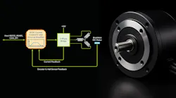
- The differences between Hall- and encoder-based position sensors for monitoring the rotor position within BLDC motors.
Real-time, low-latency control is critical to ensure smooth, stable, and fast movement for brushless DC (BLDC) motors. But maximizing the performance of BLDC motors — whether rotary or linear — requires continuous monitoring of the rotor position as it moves. The motor controller uses that to adjust the stator’s magnetic vector angle, increasing useful Q force generation while reducing undesired D force generation.
In high-performance motion control, a position-control loop compares the desired motor position with its actual position. Based on that difference, it outputs a current command proportional to the torque required to correct the error. The motor controller then distributes this current command across the motor’s windings to keep the stator vector aligned with the rotor position. Keeping everything aligned is referred to as commutation.
Several different techniques can be applied to perform this alignment. The first is called “trapezoidal” commutation. Also called six-step commutation, the trapezoidal approach uses three signals that change according to the rotor position.
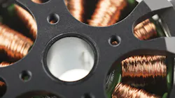
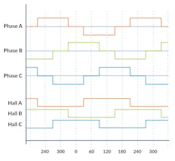
In most BLDC motors, these signal values employ Hall-based magnetic position sensors to measure the rotor position. Figure 1 shows these three signal inputs and associated motor coil drive outputs in a traditional trapezoidal commutation scheme.
Magnetic Position Sensing: Hall-Based Commutation
Each Hall-signal output is either a “high” or a “low,” and together these three signals encode six separate states within a full 360-degree electrical cycle. As can be seen in Figure 1, the motor winding drive states correspond to the Hall-signal states. They go through a repeating sequence consisting of one state of zero output command value, two Hall states of positive command, another zero output, and two states of negative command output.
>>Download the PDF of this article, and check out Parts 1 and 2 of this series
Does trapezoidal commutation provide optimal BLDC motor control? No — there are six Hall states per electrical cycle and therefore each Hall state provides a vector angle resolution of 60°, which means the Q vector is only within ±30° of its ideal value. This has two practical effects. The first is that there will be a loss of efficiency particularly as the deviation approaches the Hall-state transition edges (Fig. 2).
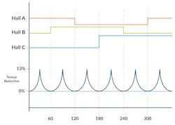
The second effect is that there will be torque discontinuities at the Hall-state transition points because the commutation vector will jump immediately by a full 60°. This can be particularly problematic if the Hall transition point happens to be near the settling position for a specific profile move. In this case, the position loop may struggle to hold a stable position because of the nonlinearity in motor torque output at this position.
Sinusoidal Commutation: All About Encoders
The next commutation technique we’ll look at is referred to as “sinusoidal” commutation, also called encoder-based commutation. This method uses a higher-resolution position encoder instead of Hall-based sensors to determine the rotor’s angle (Fig. 3).
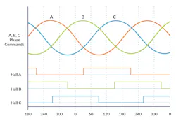
The key advantage of this approach is that it produces a sinusoidal output waveform, rather than the stair-step waveform seen with trapezoidal commutation. As a result, torque discontinuities are eliminated as the motor rotates, because the stator vector is continuously adjusted for even the smallest increments of encoder movement. Equally important, the Q force output can be optimized, resulting in more efficient motor operation.
At the same time, using encoders for commutation raises an important question: How is the initial phasing determined? For most sinusoidally commutated motors, the answer is that Hall position sensors are still present in the motor, but they’re used only for phase initialization — not for commutation.
However, another approach eliminates the need for Hall sensors. This method energizes the motor coils and observes the resulting motion to determine the initial phase. It’s often referred to as algorithmic phase initialization, or more colloquially as “wake and shake.” There’s no standard approach to executing such a phase initialization sequence, and the exact technique varies from vendor to vendor.
How popular is algorithmic phase initialization? In rotary motors, it’s relatively uncommon because Hall sensors are inexpensive and commonly installed in them. In addition, a significant issue with algorithmic initialization is that it may determine the wrong initial phasing if the motor is resting near a hard stop or if the motor experiences a high level of friction. So, the advantage of using Hall sensors to avoid these complications usually outweighs the disadvantages.
For linear BLDC motors, though, the use of an algorithmic phase initialization procedure is common. This is because embedding Hall sensors along a linear track is expensive and because linear brushless motors tend to have high-quality bearings and operate in controlled and clean environments where friction in the motor is low.
What is “Sensorless” Commutation?
The final commutation method we’ll look at is known as sensorless control. This method uses special circuitry to read the back-EMF voltage (the voltage generated by the motor windings as the motor spins) and identify characteristics of these voltage waveforms that allow the commutation angle to be determined. Example signals are shown in Figure 4.
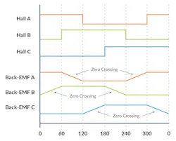
There are simple and not-so-simple ways to utilize the back-EMF of the windings to determine commutation phasing. Figure 4 represents a common and straightforward method, which is to measure the back-EMF of a floating (non-driven) leg while the other two legs are driven. The floating leg, no longer influenced by the commanded voltage output of the amplifier, contains the back-EMF voltage that can be used to determine the zero-crossing point.
Back-EMF works well under the right circumstances but has significant application limitations, the biggest being that back-EMF signals diminish in magnitude with decreasing motor velocity.
As a result, sensorless control can’t be used in positioning applications where the motor needs to be controlled at a stationary location. Another limitation is that back-EMF signal processing is susceptible to noise. This noise may come from outside the motor or from the amplifier — typically a pulse-width-modulation (PWM) switching bridge — used to apply voltage commands to the motor’s two active windings.
Nevertheless, in velocity-control applications, sensorless BLDC motor control has seen significant adoption for applications in controlled environments, where load-related torque perturbations aren’t present, friction is low, and the velocity profile executed is constant or slow-changing. Examples of such applications are hard-disk spindles, bar-code scanners, and ceiling fans.
Bearing the above in mind, sensorless commutation can best be viewed as an all-in-one velocity control technique for BLDC motors, rather than as a truly separate commutation method that can be combined with a position-loop or velocity-loop control function.
In BLDC motors, commutation is still only one of several functions that must be carefully coordinated to maintain smooth, balanced motion. Part 4 of this series will examine everything that happens after commutation: the current-control loop that measures the actual current in each winding, and the amplifier, which uses power switches to adjust the applied voltage to match the commanded current as closely as possible.
>>Download the PDF of this article, and check out Parts 1 and 2 of this series
About the Author

Chuck Lewin
Chuck Lewin, Founder and CEO, Performance Motion Devices Inc.
Chuck Lewin is Founder and CEO of Performance Motion Devices Inc. In 1992, Lewin developed a motion control on an IC technology to found PMD. In less than a year, the company released its first IC multi-axis motion processor with functions previously only on board-level motion control products. In 2024, the company introduced its ION/CME N-Series PCB-mountable drive, delivering integrated motion control, network connectivity, and power amplification in a single module.
Today, the company manufactures motion controls for servo and step motors with CAN, serial, SPI, and Ethernet communications—and capable of S-curves, synchronized multi-axis contouring, precision torque control, field-oriented control, and many other advanced capabilities.
Comment About the Article
To join the conversation, and become an exclusive member of Electronic Design, create an account today!

Leaders relevant to this article: