How To Control Brushless Motors (Part 4): Current Control
What you'll learn:
- How current-control loops in BLDC motors improve performance and efficiency while protecting against overcurrent conditions.
- The differences between current-control loops, field-oriented control (FOC), and voltage-mode approaches, including their tradeoffs.
- How motor amplifiers use PWM switching and current sensing to deliver efficient, cost-effective, and highly precise motion control.
In brushless DC (BLDC) motors, the current controller assumes one of the most important roles: It ensures that the commanded values for each motor winding — output by the commutation module — results in the right amount of current flowing through those windings. By directly regulating current, it’s possible to more precisely control the behavior of the BLDC motor, enabling higher performance and efficiency.
One of the main advantages of current control is its ability to prevent potentially dangerous overcurrent conditions, particularly when the motor isn’t yet moving. To achieve high spin rates and fast acceleration, the coils of BLDC motors often have low resistance values. Without a current-control scheme, applying the motor-drive voltage when the motor is at a standstill might generate a large and damaging current spike.
For motor controllers using a position-control loop, another benefit of current control is that it increases the effective bandwidth of the motor positioning function and makes the position-control task easier. These benefits stem from the fact that the relationship between the voltage used to drive the motor’s windings and the resulting current flow through the winding isn’t a direct one. It can, in fact, be relatively complex.
Why doesn’t a voltage at the motor winding result in a proportional amount of current flow? What’s the disconnect? Back-EMF is one effect that can alter the relationship between the drive voltage and the current flow through the winding. When motors spin faster, the effective net voltage seen by the winding decreases due to back-EMF. The current controller handles that by boosting the drive voltage as needed to achieve the commanded current.
>>Download the PDF of this article, and check out the other parts of this series


Another issue is the delay in current flow through the coil due to the coil’s inductance, which is the tendency of a wire coil to resist changes in the current flowing through it. This delay can rob a motor of its full capability to perform time-critical moves such as high-speed pick-and-place operations in electronics manufacturing. Active current control can overcome this limitation by briefly boosting the voltage to achieve faster current rise (or reduction) times.
Current Control from Inside a Position-Control Loop
A wide range of current control schemes are used with BLDC motors. However, the industry standard for high-end motors controllers, particularly those that function inside a position-control loop, is a PI (proportional, integral) current-loop controller. A PI control flow diagram is shown in Figure 1. The PI filter operates on the current error, which is the difference between the commanded current and the measured current for each winding.
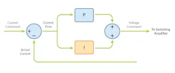
Like the position loop discussed in previous sections, the Kp and Ki gain factors of the PI filter must be specified. However, tuning the current loop is generally a straightforward process, and most motion-control vendors provide an auto-tuning function to do it.
Figure 2 presents an example of actual current waveforms from a well-tuned PI current loop, in this case from PMD’s ION/CME N-Series Digital Drive, a general-purpose positioning BLDC motor controller. The commanded current waveform (in yellow) consists of a square wave at 100 Hz and the graph shows that the actual current (in green) closely tracks the commanded current without ringing or excessive overshoot.
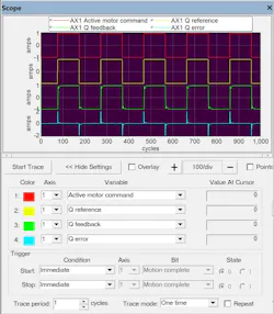
Note that Figure 2 shows the current waveforms for a motor-control system using field-oriented control (FOC). We will discuss this more advanced approach to current control next.
The Capabilities of Field-Oriented Control
Field-oriented control is an important control approach for BLDC motors. While it’s a type of current control, FOC incorporates a commutation function (unlike the standard current-loop approach shown in Figure 1).
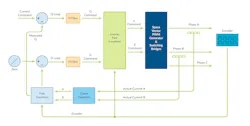
Figure 3 outlines a standard PI current control scheme driving a three-phase brushless motor. The current command output by the position loop is “vectorized” into separate current commands, one for each motor winding. As the rotor advances, the vector angle advances accordingly. These vectorized phase commands are then passed to two PI current loops that attempt to keep the actual winding current at the desired current value in those two windings.
The third phase doesn’t use a current loop. Rather, it calculates its voltage command from the expression, C = −(A+B), reflecting the fact that whatever current goes into the motor must come out.
An important characteristic of the standard PI current controller is that maintaining the commanded winding currents becomes more difficult as the frequency of motor rotation rises. This is because, as the motor rotation rate increases, so does the frequency of the sinusoidally varying current commands in each winding.
Frequency proportional lag in the current loop — insignificant at low rotation speeds — generates increasing amounts of unwanted (D) torque at higher rotation speeds. That inevitably results in a reduction of available torque.
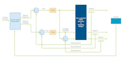
The control scheme for FOC (Fig. 4) differs in that the current loop operates independent of the motor's rotation. There’s a trick to making this work: math transforms that convert the rotating vector frame to, and from, a D and Q reference frame which is independent of rotation. These transforms are called “Park and Clarke” transforms.
The FOC approach also has two current loops. One is for the desired (Q) torque and the other for the undesirable (D) torque. The Q torque loop is driven with the commanded current output from the position-loop (or velocity-loop) controller. The D loop is driven with a command of zero to minimize the unwanted direct torque component.
What are the benefits of using the FOC approach instead of current control and commutation? The answer is higher top speed and improved efficiency at higher rotation rates. Note that for linear BLDC motors, which don’t generally move very fast in terms of electrical phases per second, there are few advantages to using FOC.
From the engineer’s perspective, using FOC is no more challenging than using standard PI current control. Implementing FOC in the controller is algorithmically complicated, but this complexity is typically hidden. To tune the FOC current-control gain settings, as before, Kp and Ki gain values need to be determined. This is typically done by an auto-tuner, which most motion-control vendors provide to customers.
FOC is a very important control technique due to its ability to increase efficiency and lower heat generation in BLDC motors at higher rotation speeds. While it once was a relatively high-end approach, new motor-control MCUs and DSPs have turned it into a relatively standard feature. It also tends to be the best approach when driving a rotary brushless motor in high-performance positioning or velocity-control applications.
Voltage-Mode Control of Brushless DC Motors
When it comes to the current-control portion of BLDC motor controllers, there’s also the possibility of not performing active current control at all. This is also called voltage-mode operation. Voltage-mode motor control is appealing first and foremost because it’s inexpensive, typically requiring only a switching bridge.
Are there safety concerns with voltage-mode control? Yes, particularly at startup or if the motor stalls. Without current control or at least current limiting, the danger is that excessive current will flow through the windings and damage the motor. This is especially true with motors designed for high-speed operation because they tend to have low motor-coil resistance.
Are there applications for voltage-mode operation of BLDC motors? Despite the limitations, the answer is definitely yes. Examples include cooling fans, pumps, compressors, high-speed surgical drills, shavers, and more. In all of these applications, explicit control of the motor velocity or torque isn’t a requirement because the motor back-EMF and/or the load that the motor drives against creates a natural bound on velocity.
Brushless Motor Amplifiers
The final component of a BLDC motor controller is the amplifier, which uses power switches to adjust the applied voltage to match the commanded current as closely as possible. While several different motor amplifier schemes exist, the most widely used architecture in high-performance position- and velocity-control applications is the triple half-bridge with leg-current sensing. A connection diagram for this digitally controlled switching amplifier is shown in Figure 5.
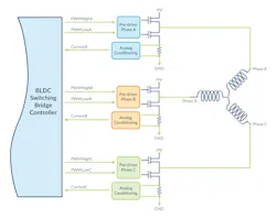
A half-bridge is a type of switching bridge that has three operating states. It can fully connect the motor-winding connection to the motor supply voltage (marked as HV in Fig. 5); it can connect the winding to ground; or it can leave the motor winding unconnected.
The signaling scheme to connect and disconnect this bridge uses separate “high side” and “low side” control signals driven with pulse-width-modulation (PWM) signals. PWM signals operate at a fixed frequency, which for small to medium BLDC motors is typically in a range of 20 to 100 kHz, and control the amplifier’s voltage output by varying the duty cycle.
Manipulating the duty cycle of PWM signals creates the illusion of analog voltage output control. For example, if the supply voltage (HV) is 24 V and the PWM duty cycle is specified as 20%, the effective voltage seen by the motor winding will be 24 V × 0.20, which equals 4.8 V.
Current measurement in this bridge architecture is accomplished using what are called dropping resistors (alternatively, analog Hall sensors can be used). These resistors output a current-proportional signal (labeled CurrentA, CurrentB, CurrentC in Fig. 5) to the current-control loop, one per motor winding. The analog outputs of each leg current sensor are filtered and then input to an analog-to-digital converter (ADC), so that the current can be used in calculations by a real-time MCU or DSP.
The design (and timing) of the switching bridge function is integrally connected to the design (and timing) of the measurement of current through each motor coil. Although well understood and widely used for at least 20 years, these timing considerations and the associated computational processing for the leg current-sensing scheme are complicated and outside the scope of this series.
Compared to motor amplifiers used in the past, today’s digital amplifiers are a marvel. The net result of this arrangement of PWM-controlled switching bridges and current-sense resistors is a highly cost-effective, extremely efficient amplifier that can provide very precise voltage amplification and very accurate current measurement.
>>Download the PDF of this article, and check out the other parts of this series
About the Author

Chuck Lewin
Chuck Lewin, Founder and CEO, Performance Motion Devices Inc.
Chuck Lewin is Founder and CEO of Performance Motion Devices Inc. In 1992, Lewin developed a motion control on an IC technology to found PMD. In less than a year, the company released its first IC multi-axis motion processor with functions previously only on board-level motion control products. In 2024, the company introduced its ION/CME N-Series PCB-mountable drive, delivering integrated motion control, network connectivity, and power amplification in a single module.
Today, the company manufactures motion controls for servo and step motors with CAN, serial, SPI, and Ethernet communications—and capable of S-curves, synchronized multi-axis contouring, precision torque control, field-oriented control, and many other advanced capabilities.
Comment About the Article
To join the conversation, and become an exclusive member of Electronic Design, create an account today!

Leaders relevant to this article: