AI for Motor Condition Monitoring at the Edge
What you'll learn:
- How edge AI sensors can detect motor faults, reducing wireless bandwidth, latency, and power consumption.
- How neural networks can identify imbalance, misalignment, and bearing defects by monitoring vibration data.
- How edge AI enables scalable predictive maintenance while extending battery life in wireless monitoring systems.
Predictive maintenance is a key pillar of Industry 4.0, allowing for early detection of faults in everything from pumps propelling liquid-cooling systems and motors driving industrial automation to giant turbines for generating power. Traditional forms of condition monitoring rely on centralized processing, where raw sensor data streams into a host system, located in either a gateway or the cloud. While effective, this approach imposes significant constraints on network bandwidth, latency, and power.
Implementing an edge-AI-based sensor with local inference capabilities can help address these challenges by processing data closer to the motor itself. By reducing the communication overhead, these sensors can reduce latency, improve overall system efficiency, and extend battery life.
However, designing a real-time system requires carefully balancing the accuracy and reliability of AI-based fault detection with the stringent power constraints of battery-operated sensors.
This article presents the practical implementation of an edge AI model for motor fault detection embedded in the Voyager4 wireless condition-monitoring platform. The model is trained to learn normal motor behavior and identify faults associated with imbalance, misalignment, and bearing defects. The results demonstrate that edge AI can achieve reliable fault detection while significantly reducing power consumption, enabling scalable predictive maintenance solutions for industrial environments.
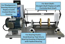
The dataset includes three-axis (X, Y, Z) vibration data sampled at 20 kHz, enabling analysis of both low- and high-frequency signal components. The vibration signal can be modeled as:

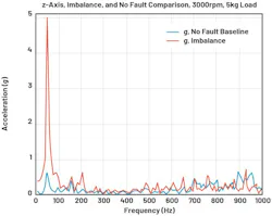
Fault conditions introduce deviations such as harmonic distortion, amplitude modulation, and high-frequency transients, all of which can impact the motor’s performance. For instance, mechanical imbalances between the rotors can increase the amplitude of frequency used to drive the motor (Fig. 2). At the same time, misalignments within the motor can introduce harmonics, while bearing defects may result in high-frequency spikes. These differences form a basis for anomaly detection.
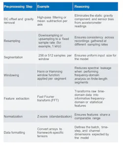
The pre-processing pipeline used for the Voyager autoencoder, outlined in the table, includes segmentation into fixed-length windows, normalization, and formatting the data into tensors for training and inference. However, there’s no universal formula for maximizing model performance. For example, fast Fourier transform (FFT) isn’t the only method for feature extraction, but it tends to be more effective when evaluating the model’s accuracy.
AI-Driven Fault Detection Moves Inside the Motor
At the core of Voyager4’s AI-driven fault detection capabilities is an autoencoder neural network. The autoencoder, as illustrated in Figure 3, is trained exclusively on healthy motor data. The model learns to reconstruct normal vibration patterns with high fidelity.
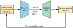
When presented with data from a faulty motor, the reconstruction error increases, enabling the system to flag anomalies indicative of imbalance, misalignment, or bearing defects.
More specifically, autoencoders learn to reconstruct their input at their output. The autoencoder is trained to maximize information kept after dimension reduction through encoding and to minimize reconstruction loss (RL) after decoding. As a result, the encoder and decoder structures are forced to learn the best encoding-decoding scheme in the training process.
Autoencoders are well-suited to an unsupervised learning approach using healthy signal reconstruction, and they provide a high RL when a fault case is encountered that deviates from healthy data.
The input to the autoencoder is a 2D tensor of shape (256, 3). There are 256 channels each of width 3. Therefore, each channel contains one frequency bin value from each of the vibrational axes.
Convolutional-neural-network (CNN) filters work depth-wise across channels, so at the input layer, each filter is looking at a single axis at a time. These axes are combined internally in the model. The output data format is a 1D tensor of length 768 (three axes × 256 frequency bins). The reason is that the output layer is a fully connected layer, not a convolutional layer (Fig. 4).
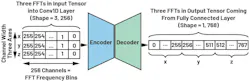
The use of a fully connected layer for the output layer (and several internal hidden layers) is to accommodate the fact that 1D transpose convolutions aren’t yet available in the target software stack. Transpose convolutions are generally used in the decoder to reconstruct the compressed representation of the data received by the decoder. Convolutional layers are used in the encoder to reduce the number of total parameters in the model (Fig. 5).
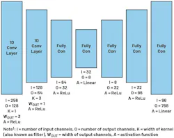
The architecture is optimized for deployment on the MAX78000 microcontroller, balancing model complexity with the stringent memory and compute constraints of edge devices.
Evaluating the Model: Using the AI to Identify Motor Faults
For model evaluation, the mean squared difference between the output and the input is the only loss function. The difference between the output and the input for a given set of data is called the reconstruction error.
Figure 6 shows histograms of the reconstruction errors for validation and anomaly data. This dataset had 10 different healthy modes of operation and 120 different modalities for faults. The fewer healthy scenarios there are to classify as healthy, the easier it will be to learn. And it’s more likely that there will be less overlap between the high reconstruction errors for healthy samples and low reconstruction errors of faulty samples. The red bar in Figure 6 shows the reconstruction error overlap where false positives and negatives can occur.
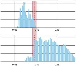
The decision threshold defines the acceptable level of false positives and negatives for the application (shown as a dashed red line in Figure 6). For example, a critical motor in a key industrial process would set a low decision threshold to reduce the number of false negatives that are reported. The full dataset used for this project, along with detailed guidelines for the data loading and pre-processing steps, is available on GitHub.
Conclusion
Everything comes together in a complete, practical pipeline for deploying an edge-AI-based model for motor condition monitoring. By combining high-resolution vibration sensing with an optimized convolutional autoencoder, the system effectively learns normal motor behavior and detects deviations associated with common faults such as imbalance, misalignment, and bearing defects.
Using an autoencoder model enables the use of RL as an anomaly detection metric that doesn’t require labeled fault data. Thus, it’s particularly well-suited to industrial environments where fault examples are limited.
References
“Motor Fault Detection at the Edge Using MAX78000.” GitHub.
Richard Anslow and Chris Murphy. “How to Choose the Best MEMS Sensor for a Wireless Condition-Based Monitoring System—Part 2: How to Detect Mechanical Faults.” Analog Devices, January 2022.
>>Download the PDF of this article
 dreamstime_kpixmining_287384127
About the Author
 Richard Anslow
System Applications Engineer, Analog Devices
Richard Anslow is a senior manager within the Industrial Automation Business Unit at Analog Devices, working in the field of software systems design engineering. His areas of expertise are condition-based monitoring, motor control, and industrial communication design. He received his B.Eng. and M.Eng. degrees from the University of Limerick, Limerick, Ireland. Recently, he completed a postgraduate program in AI and ML with Purdue University.
Tom Sharkey
Senior Engineer, Analog Devices Inc.
Tom Sharkey is a systems applications engineer in the Industrial Edge, Motion, and Robotics Unit at Analog Devices. Tom received a bachelor’s degree in electronic and computer engineering from the University of Limerick in 2020. He has experience in condition monitoring sensors, firmware/software design, and motor control.
Related
dreamstime_kpixmining_287384127

Comment About the Article
To join the conversation, and become an exclusive member of Electronic Design, create an account today!
 Leaders Logo
Leaders relevant to this article: