The Many Paths to Electronic Prototypes
What you’ll learn:
- The benefits of hardware prototyping.
- Advantages of having custom-designed prototypes.
- Packaging considerations to make when prototyping.
- Benchtop tools available for in-lab prototype assembly.
The range of tools available to assist with the introduction of new products has never been more extensive. Thanks to the improved performance of desktop computer hardware, access to cloud resources, and the availability of advanced simulation tools, engineers can model electronic-system performance to a high level of detail in the virtual domain as well as the physical domain through prototypes.
In the virtual domain, it’s now possible to not just analyze the frequency capabilities and noise levels of mixed-signal circuits—even their electromagnetic compatibility can be assessed before a single integrated circuit is placed on a printed circuit board (PCB).
Such simulations can provide a high degree of confidence in design without the need for investment in high-performance test equipment to perform extensive analysis of a circuit design. Simulation can help ensure that mistakes in circuit layouts are avoided so that the final test can be performed quickly and easily using rented facilities.
Affordable tools, such as those provided by Altium and National Instruments’ LabVIEW, provide not only devices to perform Spice simulations that are vital for assessing the analog performance of a basic schematic, but tasks that determine how well a design will function once placed and assembled. PCB stackup calculators, for instance, can determine the parasitics associated with routed traces, and signal-integrity analyzers will pinpoint potential crosstalk and noise issues.
Hardware Prototyping and Low-Volume Production
Despite the capabilities of simulation available today, there are many occasions when nothing other than a hardware prototype will do. The team may need to use hardware implementations to test assumptions that are too difficult or time-consuming to perform in the virtual environment.
For example, a software-programmed control loop may be designed to run on a microcontroller that needs to be evaluated against real-world signals in real-time to determine whether it’s stable across a range of target scenarios. A software instruction-set simulator may simply not be able to deliver results in a timely fashion or be driven by realistic input data.
Another scenario is that the performance of different antennas in a radio-frequency (RF) design needs to be evaluated. This may be better accomplished by trying different configurations attached to a hardware prototype.
Alternatively, it’s possible that the project has progressed to the point where field trials and early customer acceptance tests are required. In the context of the Internet of Things (IoT) in particular, it’s important to see how multiple devices work on a network with each other and with the cloud. At this point, the team should consider the options for prototyping and possibly low-volume production to be able to provide enough hardware to support a satisfactory field trial.
A number of options are open to the team. The best course of action will depend on a variety of factors. The choices range from adding custom I/O daughterboards to an existing single-board computer (SBC), to ordering a low-volume production run from an electronics manufacturing services (EMS) partner.
If the aim is to ensure that software will perform as expected in a hardware-in-the-loop test of core functions, it will make sense to employ a compatible SBC and create a prototype I/O card if the off-the-shelf board doesn’t have the required interfaces, or if it doesn’t perform to a sufficient level.
Even if the final design calls for a custom PCB design, possibly using a different variant of the onboard microcontroller, the prototype will deliver enough useful information to be justified and minimize any software changes for the production version. By isolating the custom I/O to a daughterboard, the team can minimize the time and cost needed to construct a viable prototype.
Custom-Designed Prototypes
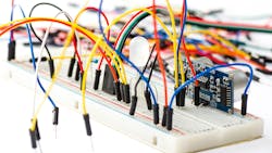
In some cases, using a combination of off-the-shelf hardware (see figure) with custom I/O will not perform as well as a custom-designed prototype. Testing assumptions about signal integrity may call for a PCB design that’s as close as possible to the final production model. Field trials will often demand hardware that fits into a highly constrained physical or power envelope.

The decision then becomes one of the capabilities of an in-house lab to construct a working prototype versus the lead times and cost of having fully assembled hardware provided by an EMS partner.
If the complexity of the hardware parts is relatively low, a breadboard-based option may be viable. This can be a suitable choice for, say, an SBC that’s combined with a custom I/O daughtercard, because less components need to be assembled onto the breadboard.
If the components are mostly discretes, it’s easier to source through-hole devices that are compatible with breadboard platforms. Experienced distributors can advise on the packaging options open to a design team for prototyping and which support a transition to surface-mount components for final production.
Importance of Electronic Prototype Packaging
Packaging choices represent an important factor in determining whether it’s better to order fully populated prototypes from an EMS provider or perform some of the assembly in the design team’s own lab. A commonly used approach is to use tools such as those from Altium and Autodesk to design a PCB for a prototype, and then assemble the necessary components for the design in the lab. With this approach, the team relies on a combination of design insight and access to low-cost lab tooling and test.
In contrast to the breadboard option, designers can choose to employ not just components in through-hole packages, but those designed for surface-mount assembly. However, there are practical restrictions on what can be realistically assembled and soldered in a lab environment. This is simply due to the difference in accuracy between human hands and automated pick-and-place equipment, which can position tiny components with sub-millimeter accuracy.
To some extent, the surface tension of a hot solder, assuming it’s deposited reasonably accurately on the surface of a PCB, will help to pull small discretes into place. However, it’s clearly easier to mount, by hand, discretes that come in the larger surface-mount packages or their through-hole versions versus 0402 or smaller surface-mount devices.
Similarly, surface-mount devices with pins around the edge, such as quad flat-packs (QFPs), will be easier to place and solder in a lab environment compared to those using ball-grid arrays (BGAs). That’s because the engineer can see whether the pins are correctly aligned before soldering.
Many surface-mount ICs come in a variety of packages so that the QFP variant can be utilized for low-run production and prototyping with the BGA, or chip-scale package variants used in production. Distributors with design-in support experience can advise on which components are suitable for a twin-track approach. In such an approach, the prototype uses one form and the final PCB uses the lower-cost or more compact variant. Simulation tools will help identify any potential changes in signal integrity or I/O routing that may be needed to accommodate the transition from prototype to production.
Benchtop Tools to Facilitate In-Lab Assembly
A variety of everyday benchtop tools, such as fine-tip soldering irons, will facilitate in-lab assembly. Today, the microscope is an essential aid to mounting fine-pitch devices on bare PCBs. The stereo-zoom microscope typically provides ring illumination to assist with the precision placement of components and support post-reflow inspection.
A solder-paste injection is another important tool. Typically, this uses compressed air to apply controlled amounts of solder paste to the PCB in a repeatable way. The high level of control over dispensing greatly eases the mounting of packages, such as QFP, with large numbers of closely spaced pins.
For the solder-reflow operation itself, an engineer may use a reflow hotplate to reflow small portions of the board at a time. Alternatively, all of the components may be mounted before transfer to a benchtop reflow oven.
As some level of soldering failures will be inevitable for all but the most experienced engineers, test and rework tools will be vital. Hot plates and hot-air tools assist with the removal of misaligned or failed components ready for a resoldering operation. For test, a multimeter is an important tool as it can be used to probe any of the visible pads and surface traces when checking for connectivity.
On that front, Newark stocks a comprehensive range of lab tools made by specialists such as Metcal and Weller. It also has the in-house expertise to advise on their capabilities for prototype assembly and rework.
Bringing It All Together
There are many options and tradeoffs open to design teams when it comes to creating and using prototypes during product development. Experienced distributors can provide valuable advice on sourcing components suitable for lab assembly and the best form of delivery to EMS partners, as well as how the package and supply options can be changed to suit final production. In addition, they can guide teams on the best tools to use in the lab when in-house assembly is the best direction to take. All that’s needed is the imagination and skill of an engineer to turn a product idea into reality.
About the Author
Simon Meadmore
Global Head of IP&E, Newark
Simon joined Newark’s global businesses in 2004 and is responsible for global supplier and product strategy. He was previously the head of Newark’s Global Interconnect, Passives and Electromechanical product segment. Simon has also managed Newark’s Semiconductors business unit and held supplier facing roles in EMCO and Passive product segments.
Before joining Newark, Simon spent five years at Pace Micro Technology, a set-top box OEM, as a senior buyer for memory products and spent nine years working for a small electronics contract manufacturer. Simon is a member of the Chartered Institute of Purchasing and Supply (CIPS).
Comment About the Article
To join the conversation, and become an exclusive member of Electronic Design, create an account today!

Leaders relevant to this article: