Anyone who has worked on a system design lately knows that creating a printed-circuit board (PCB) is no longer simple. Differential signals and multiple layers are the norm. RF is needed for Bluetooth, Wi-Fi, Zigbee, Z-Wave, and more. Signal integrity is as important as making sure the right pins are connected together.
This file type includes high resolution graphics and schematics when applicable.
Likewise, boards are more complicated. More layers are often needed to address the density of systems-on-chip (SoCs) that have hundreds of balls packed into an ever-tighter space. This complexity lends itself to automatic routing, but many designers still prefer manual routing because it can address issues that are sometimes hard to quantify to a program.
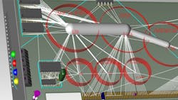
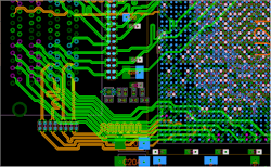
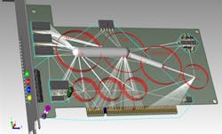
Companies like Altium, Cadence, Zuken, and Mentor Graphics have PCB layout programs designed to address these issues. Mentor Graphics’ latest Xpedition xPCB Layout simplifies interactive routing of differential signals (Fig. 1). Its high-level, hierarchical placement tool can operate in 2D and 3D modes (Fig. 2).
Xpedition’s 3D mode and mechanical enhancements allow designers to address the 3D aspects of a design, not just the circuit layout issues. The system can perform automatic placement and management. Yet its auto-assisted routing and customizable multi-pass autorouting impressed me the most when the company demonstrated its latest software. Auto-assisted routing is an interactive process. Just start from a pin and drag the cursor to about where the path should be and watch the results.
Running differential pairs was just as easy. The “multiplow” process lets a designer adjust a collection of paths like a data bus in one step. It keeps the paths in sync with each other, providing the nice, parallel layout that is usually the result of a fully manual but time-consuming process. The system can even be programmed to allow arcs or angles when required for tight routing like around ball-grid array (BGA) balls. The push and shove manual/auto-assist works in 3D mode with objects like chips too.
I have not laid out a board in a couple years. But if it is this easy, I might try again soon.
About the Author
William Wong Blog
Senior Content Director
Bill's latest articles are listed on this author page, William G. Wong.
Bill Wong covers Digital, Embedded, Systems and Software topics at Electronic Design. He writes a number of columns, including Lab Bench and alt.embedded, plus Bill's Workbench hands-on column. Bill is a Georgia Tech alumni with a B.S in Electrical Engineering and a master's degree in computer science for Rutgers, The State University of New Jersey.
He has written a dozen books and was the first Director of PC Labs at PC Magazine. He has worked in the computer and publication industry for almost 40 years and has been with Electronic Design since 2000. He helps run the Mercer Science and Engineering Fair in Mercer County, NJ.
- Check out more articles by Bill Wong on Electronic Design
- Bill Wong on Facebook
- @AltEmbedded on Twitter


