Stay Ahead of System Faults with High-Performance Voltage Supervisors
What you'll learn:
- How advanced voltage supervisors detect and respond to power-related faults, including undervoltage events, power-supply failures, and operation outside voltage specifications.
- How enhanced supervisory features — power‑fail warnings, window monitoring, watchdog timers, and manual reset — can improve reliability and robustness in MCU-based systems.
- How battery‑backup and memory‑protection functions help maintain operation and prevent data loss during power interruptions or due to instability in the system.

High-performance voltage supervisors are used to put systems into reset mode during the detection of fault conditions, such as in a power supply, to avoid system errors or other malfunctions. Fast detection of faults is critical to ensuring the reliability of systems based on microcontrollers (MCUs) or other logic chips with strict power-supply requirements and limitations. However, things don’t end when putting these systems in reset mode during an undervoltage condition and expecting everything to run smoothly over time.
Aside from power requirements, system design flaws and component imperfections and limitations, if neglected, can affect the overall system performance, making it unstable and less dependable.
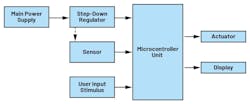
For instance, consider the typical architecture of an MCU-based system, sketched out in Figure 1. These kinds of applications often encounter problems brought about by device limitations like frozen MCUs and software code hang-ups, complications triggered by the environment such as sudden power failures, and faults from design flaws (e.g., operation outside specifications among others).
Supervisory circuits continue to evolve, incorporating improved functionalities significant in addressing these limitations.
Protecting Systems from Imminent Power Failure
Most of the power used by processors, sensors, and other “downstream” circuits comes from a main power supply. Failures in the “upstream” supply can cause these circuits — and the entire system — to eventually fail. If not anticipated in advance, such power failures can induce significantly undesirable effects on the system, including damage to the hardware. Failures can also lead to system malfunction, data loss, and damage that may incur additional repair costs or, worse, a temporary shutdown of operations.
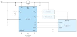
However, failures in the downstream circuits due to the main supply are hard to detect ahead of time, especially if the step-down DC-DC regulator (Fig. 2a) supports a wide acceptable input range. The DC-DC regulator can continue operating within its range without issuing any warnings to the whole system.
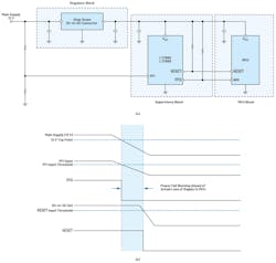
The power-fail warning circuit is designed to detect an imminent failure in the system’s upstream supply. It generates a power-fail output (PFO) to serve as a sort of early-warning system.
The component values can be chosen such that the voltage at PFI falls below the reference several milliseconds before the DC-DC regulator output falls. This setting gives the MCU its power if it goes out completely (Fig. 2b). The PFO signal is usually used to interrupt the MCU so that it can execute necessary processes and shutdown procedures.
A wide range of supervisory circuits come with this feature, including the MAX16020, MAX16033, ADM69x, LTC6911-x, and products in LTC69x family like the LTC692 and LTC693. Other power system diagnostics, such as monitoring battery voltage levels in battery-powered devices, can be performed using this power-fail warning feature.
Ensuring Operation Within Power-Supply Specifications
In systems where tight voltage regulation is required and overvoltage faults can cause catastrophic damage, a window voltage supervisor is necessary. For instance, complex electronics systems are frequently based on FPGAs, which have tight power-supply regulation requirements. Operating outside the FPGA’s power-supply window specification may lead to an unoptimized design that causes excessive power dissipation and shortens the lifetime of these devices.
>>Download the PDF of this article

Window voltage supervisors also play a significant role in achieving a certain level of system safety. They’re often used as power-supply diagnostics to detect undervoltage (UV) and overvoltage (OV) faults and trigger a mechanism to bring the system into a safe state.
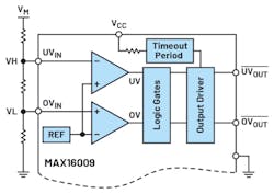
In many cases, window voltage supervisors come with dedicated UV and OV output and resistor-configured trip points (Fig. 3), which is implemented with the MAX16009. However, this is only one of many architectures for a window voltage supervisor; other implementations are available to fit different preferences in applications. (For more details, see “Optimize Your System Design with the Right Window Voltage Supervisor”).
Watchdog Timers: Watching for Inactivity and System Hang-Ups
Watchdog timers give voltage supervisors the ability to monitor microprocessor (MPU) inactivity in addition to monitoring the supply voltage, thus preventing further system hang-ups.
Several factors can cause an MCU to freeze, stick, and stop its operation. These snags can be due to power-supply problems, electrical interference, and software or coding issues. Optimizing power-supply design and implementing voltage monitoring helps improve noise and stability performance.
Instability in the power supply is usually one of the causes of rising device temperature and slowed-down device performance, leading to system hang-ups. There are various ways for engineers to address electrical interference in a design, increasing the system’s immunity to these intrusions and thus reducing the risk of the MCU freezing up.
At the same time, system inactivity can also stem from software issues, such as being locked up in an infinite loop, processes that are too long, or logic errors in the code. These problems are detectable with watchdog timers.
Clock signals coming from the MCU or MPU are monitored within a specified time frame. Failure to provide clock signals within the time frame indicates that the system is inactive or spinning its wheels with complex software. The watchdog timer provides an output signal, which can be a watchdog output (WDO) or the reset output signal.
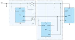
Figure 4 shows an application use case in wireless sensor nodes, where watchdog timers monitor the system's inactivity and its output triggers a redundant reset mechanism — a soft reset and a hard reset through power cycling. Note that the second watchdog, WD2, has a longer watchdog timeout period and is used to drive a high-side MOSFET switch for power cycling if inactivity persists.
Watchdog timers are becoming more stringent in monitoring a processor’s activity. The challenge/response watchdog, which is a more recent architecture from Analog Devices, requires an MPU or MCU to perform a task or computation to ensure that it’s fully operational.
In this type of watchdog timer, such as the MAX42500, there’s a key-value register within the watchdog timer IC. The MCU uses the value to compute the appropriate response. This watchdog eliminates the possibility of being stuck in a routine that’s just giving a mere periodic signal.
One of the other architectures to watch is the “window watchdog.” The device is very similar to a traditional watchdog timer, but it features a service cycle that’s split into durations called windows. Since a service is only valid at certain times in the windowed cycle, it requires more precise timing for valid services.
Hitting Reset: Using Voltage Supervisors to Enable Manual Reset
The ability to put the system into reset mode, in addition to automatic triggers such as voltage faults and watchdog timers, is often desirable. Manual reset (MR) allows users to perform activities such as testing, debugging, and addressing software issues without needing to do a hard reset or power off the system.
The manual reset feature also enables users to force a restart during system lockup without recycling power. Doing this will save time and energy, as reinitialization of the whole system isn’t needed. This is typically used along with an emergency stop, ensuring a controlled shutdown when necessary.
In applications like the circuit in Figure 5a, when the MR pin is used with a mechanical interface (a switch, for instance), or even with external logic that can be influenced by noise and glitches, a reset output can be falsely triggered.
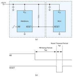
To prevent this scenario, internal circuit techniques are being implemented in manual reset features such as the debounce circuit and long manual reset setup period requirement. Figure 5b shows how a manual reset setup period in the MAX6444 works and ensures a reliable input signal. (For more details on addressing false triggers in manual reset, see “How Voltage Supervisors Address Power Supply Noise and Glitches.”)
Continuing Operation and Avoiding Data Loss During Power Loss
Some applications require nonvolatile memory to preserve data across power cycles. This requires the contents of RAM and other critical system functions to be continuous even when the power supply is lost.
Supervisory circuits that have a battery backup feature — for instance, the circuit seen in Figure 6 — can address this problem. When the input supply VCC is present, it’s routed to the output VOUT. If the VCC fails, the battery voltage (VBATT), in this case, is routed to VOUT. The switchover circuit compares the input supply voltage to the VBATT input and connects the output to whichever is higher. Usually, hysteresis is present, which prevents repeated and rapid switching if the VCC falls very slowly or remains nearly equal to the battery’s voltage.
The VOUT is able to supply a limited current from VCC through an internal switch. If more current is required under heavy loads, an external PNP transistor can be added. When VCC goes back to proper regulation and becomes higher than VBATT, the BATT ON output goes low.
Complementing the battery backup feature is the active-low chip-enable (CE) gating, which protects data and prevents it from being corrupted. The active-low CE line from a microprocessor or address-decode logic is routed through the supervisory chip instead of going directly to the SRAM. This signal passes through the supervisor unaffected.
During reset, the CE line is forced high to disable access to the memory, protecting the SRAM contents from unwanted data corruption and erroneous writing. In many cases, flash memory can be used to replace battery backups. However, numerous systems still can take advantage of this feature.
While some supervisory circuits come with each of the features discussed previously, other parts come with all of the features together in one component, thus offering a more comprehensive and complete solution.
Supervising a Voltage Supervisor is Key for System Reliability
While detecting undervoltage faults in voltage supervisors increases system reliability, other diagnostic functions and mitigating features can be added to handle various system faults and further enhance system robustness and dependability. Other features such as power-fail warning, window voltage monitoring, watchdog timer, manual reset, and battery backup help address possible scenarios that could arise and cause errors due to limitations of MCU- and MPU-based systems.
Monitoring these scenarios — and taking action to avoid the most catastrophic outcomes — helps give a higher level of confidence to system designers as well as end users.
References
Niño Angelo Pesigan, Ron Rogelio Peralta, and Noel Tenorio. “Driving a High-Side MOSFET Input Switch Using Active Low Output for System Power Cycling.” Analog Dialogue, Vol. 58, No. 1, February 2024.
“The Basics of Windowed Watchdogs.” Analog Devices, December 2021.
Bryan Borres and Christopher Macatangay. “Improving Industrial Functional Safety Compliance with High Performance Supervisory Circuits: Safety Critical Features—Part 3.” Analog Dialogue, Vol. 59, June 2025.
Noel Tenorio. “How Voltage Supervisors Address Power Supply Noise and Glitches.” Analog Dialogue, Vol. 57, November 2023.
“Supervisory Circuits Keep Your Microprocessor Under Control.” Analog Devices, April 2002.
>>Download the PDF of this article
About the Author
Noel Tenorio
Product Applications Manager, Analog Devices
Noel Tenorio is a product applications manager in the Industrial, Power, and Precision Group handling high-performance supervisory products at Analog Devices Philippines. He joined ADI in August 2016. Prior to ADI, he worked as a design engineer in a switch-mode power supply research and development company.
He holds a bachelor’s degree in electronics and communications engineering from Batangas State University, as well as a postgraduate degree in electrical engineering major in power electronics and a Master of Science degree in electronics engineering from Mapua University.
Comment About the Article
To join the conversation, and become an exclusive member of Electronic Design, create an account today!

Leaders relevant to this article: