Safety Implications of Bidirectional Power Flow in 120-V AC Regenerative Electronic Loads
What you’ll learn:
- What are electronic loads (e-loads)?
- How to overcome inefficiency of regenerative e-loads.
- What are potential hazards with regenerative e-loads?

An electronic load, or simply e-load, is a programmable test instrument that draws controlled amounts of current or power to evaluate the performance and power consumption of power sources. Electronic loads are widely used to test power supplies, batteries, chargers, DC-DC converters, solar panels, fuel cells, server power systems, and other devices under test (DUTs) that generate or deliver electrical power.
Introduction to Electronic Loads
The e-load precisely controls current, voltage, resistance, or power to emulate real-world operating conditions of the DUT while safely consuming the energy supplied by the DUT. The most common type of e-load is called a dissipative e-load.
A dissipative e-load converts the electrical energy it absorbs into heat, which is dissipated into the air, typically using power transistors and heatsinks. Its relatively simple architecture makes it inexpensive, while also providing fast dynamic response for transient testing of power supplies, batteries, converters, and other power electronics. However, 100% of absorbed power is wasted as heat and thus a dissipative e-load operates at 0% efficiency, where efficiency is power out / power in.
Dissipating this heat drives substantial cooling requirements and increases facility operating costs. As power levels increase, the need for larger heatsinks, fans, and HVAC infrastructure can become a significant challenge.
Despite these limitations, dissipative e-loads remain a popular and practical choice for many laboratory and production test environments. It’s where simplicity, reliability, and lower acquisition cost outweigh the benefits of energy recovery.
How Does an E-load Work?
The most basic e-loads can operate in constant current (CC) or constant voltage (CV). Some e-loads provide constant resistance (CR), constant power (CP), or even constant impedance (CZ), but all of these modes are generally derived from the basic CC or CV function.
A CC e-load is used to load down a CV source, such as the output of a DC/DC converter. A CV e-load would be used to load down the output of a CC current source.
Looking more closely at the CC programmable e-load (Fig. 1), the e-load controls the amount of current flowing by adjusting the RDS of the FET. The actual current is sensed by the series resistor (current shunt). This signal across the shunt is amplified, compared against a DAC voltage used to program the e-load to the desired CC level, and fed back into the gate of the FET to create a regulated constant current.
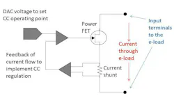
If too much current is flowing, the feedback circuit will adjust the gate voltage to increase the RDS and reduce the current flow. If not enough current is flowing, the feedback circuit will adjust the gate voltage to reduce the RDS and increase the current flow. If the e-load can’t pull enough current to achieve the CC value, the feedback circuit will cause the gate to turn on full and set RDS to its lowest value, effectively turning the FET into a short.
The maximum current will flow based on I = V/R, where V = VOUT of the DC-DC converter and R = (RDS(on) of the FET + Rshunt). When this limit is hit, e-load will not be in CC, as it can’t drive the current to the programmed CC value. Instead, the e-load will go unregulated with a near short across its input terminals. This near short is the minimum resistance of the e-load and it’s often specified as the e-load’s “minimum on-resistance” or “short circuit resistance.”
For more information about e-loads, including schematics and theory of operation, see the article “Why Can’t You Put Electronic Loads In Series To Get More Voltage?”
Regenerative E-loads Overcome Inefficiency
A regenerative e-load performs the same test function as a dissipative e-load. However, instead of converting the absorbed energy into heat, it converts the energy into usable ac power and returns it to the utility grid. Internally, the e-load operates as a bidirectional power converter, precisely controlling voltage, current, resistance, or power while transferring the absorbed energy through an inverter stage.
By testing high-power devices without generating large amounts of waste heat, regenerative e-loads reduce energy consumption, cooling and HVAC requirements, and facility operating costs. Recycling the energy rather than dissipating it in resistive elements also makes regenerative e-loads a more sustainable and cost-effective solution for high-power test applications.
In practice, dissipative e-loads remain the preferred choice for many laboratory and production environments below 10 kW because of their lower purchase price and simplicity. Regenerative e-loads become increasingly attractive as power levels rise above 10 kW and on up to megawatts operating for long durations, where energy savings and reduced cooling requirements can quickly offset the higher initial investment (Fig. 2).
- Comparing dissipative to regenerative e-loads.
Regenerative E-Loads are Grid Power Sources
As stated above, dissipative e-loads dissipate and waste the energy consumed during test. In contrast, a regenerative e-load is actually a power source supplying power to the grid. It must be connected to the electrical grid through a high-power connection so that absorbed energy can be safely converted and returned to the utility.
However, supplying power back to the grid drives additional design requirements, operational behaviors, installation complexity, utility interconnection and regulatory considerations, safety compliance requirements, and facility infrastructure costs compared to simpler dissipative load solutions. For more information on grid-connected devices, see “Modernizing the AC Power Grid for Future Stability.”
Most regenerative e-loads operate at power levels over 5 kW, so their grid connection will be a three-phase high-current and high-power connection. In the U.S., these grid connections will be 208 V AC phase-to-phase 3Φ AC or 480 V AC phase-to-phase 3Φ AC. For these high-power connections, building electrical code requires installation to be hardwired such that the regenerative e-load must be on its own dedicated circuit with a breaker.
But what would happen if the regenerative e-load was a low-power e-load, perhaps at 500 to 1500 W? Since a regenerative e-load of this size would put less than 20 A back on the AC line, it would be able to regenerate AC power back onto the line using a standard 120 V AC. However, you may not be able to find a 120-V AC regenerative e-load that’s safety certified.
Potential Hazard with Regenerative E-loads
The safety issue isn’t related to its electrical behavior or lack of compliance with regulations for putting power back on the grid. The safety issue is caused by human behavior.
A low wattage 120-V AC regenerative e-load would be outfitted with a standard AC line cord that could plug into a standard wall outlet or power strip. This would be a great usability feature, as you would be able to plug it in anywhere and it would place that power back on the ac line … and this is where the safety issue arises.
Let’s say you plan to plug into a standard power strip. These are protected against overload by a circuit breaker in the power strip. But this breaker is located “between” the AC outlets on the strip and the strip’s AC cord, such that if any device pulls too much current, the breaker opens to protect against excessive current flow and potential fire.
This protection scheme works because the power only flows in one direction: from the AC grid through the wall outlet to the power strip’s cord, through the breaker, and into the devices that are plugged into the power strip.
Now, if you put a regenerative e-load into the power strip, current can flow between two devices plugged into the power strip. That current never reaches the circuit breaker. As a result, there’s no protection against excessive current. Let’s look at an example:
- You have three 800-W power supplies connected to a power strip
- Together, they’re 2,400 W and so they exceed the power strip rating. If you try to use them at full power, no hazard will occur because the power strip breaker will blow.
- Now, additionally, plug in a 1,000-W regenerative e-load.
- The total is now 2,400 W of source power minus 1,000 W of regenerated power, yielding a total net power of 1,400 W so that the breaker will not trip, but current flowing inside the power strip can exceed the amperage rating of the power strip.
- This creates a fire hazard.
Now, you may be thinking “Why not prevent the hazard by just stating that the regenerative e-load must be used on a dedicated AC circuit protected by a circuit breaker?” That’s fundamentally how a larger, high-powered regenerative e-load would need to be professionally installed. While the regenerative e-load manufacturer could make this declaration in their documentation, a concept called reasonably foreseeable misuse comes into play.
The standard safety and risk-management term for predictable user actions outside the intended operating instructions is reasonably foreseeable misuse. During product design and safety evaluation, manufacturers must consider these predictable actions and mitigate any resulting hazards through inherently safe design, protective measures, or, where adequate, warnings and instructions.
Even if the documentation says the regenerative e-load must be on dedicated branch, there’s no practical, physical way to ensure that the user will connect the regenerative e-load via its own dedicated branch. Thus, it’s a foreseeable misuse that the user will not connect the e-load to its own dedicated branch.
In the end, the NRTL will withhold certification if:
- The misuse is considered reasonably foreseeable. Note that plugging a regenerative e-load into a power strip is foreseeable, even if the documentation says don’t do it. In fact, a fundamental principle in modern product safety is that warnings and instructions are the weakest form of risk control.
- The resulting hazard is serious (fire, shock, injury).
- The manufacturer can’t adequately mitigate the risk.
Summary: Safety Implications of Bidirectional Power Flow
Electronic loads simulate real-world power consumption by controlling current, voltage, resistance, or power during testing. Dissipative e-loads are simple and economical but they waste absorbed energy as heat, while regenerative e-loads return energy to the grid, reducing energy and cooling costs in high-power applications.
However, low-power 120-V AC regenerative e-loads connected to standard outlets or power strips can create current paths that bypass normal overcurrent protection. The result can be dangerously overheated wiring and a serious fire risk — even when the circuit breaker never trips. As a result, 120-V AC low-power regenerative e-loads will not get safety certified and therefore will not be available from reputable e-load vendors.
>>Download the PDF of this article
 promo_id_5883043__helder_almeida__dreamstime
About the Author
 Bob Zollo
Solution Architect for Battery Testing, Electronic Industrial Solutions Group
Bob Zollo is solution architect for battery testing for energy and automotive solutions in the Electronic Industrial Solutions Group of Keysight Technologies. Bob has been with Keysight since 1984 and holds a degree in electrical engineering from Stevens Institute of Technology, Hoboken, N.J. He can be contacted at [email protected].
Related
promo_id_5883043__helder_almeida__dreamstime

Comment About the Article
To join the conversation, and become an exclusive member of Electronic Design, create an account today!
 Leaders Logo
Leaders relevant to this article: