What you’ll learn:
- Why a better current sensor for EVs is advantageous.
- How a diamond-based quantum sensor may be suitable.
- Test results for this sensor.
Measuring a physical attribute such as voltage or current with high precision and have the ability to detect small changes over a wide dynamic range is a pervasive real-world sensing challenge. This situation arises in electric vehicles, where battery current can reach a maximum of several hundred amperes while the average current is only approximately 10 A. Ordinary sensors simply don’t have an accuracy of several tens of milliamperes while maintaining a dynamic range of several hundred amperes.
Therefore, the state of charge must be estimated with an ambiguity of approximately 10%, which makes the battery usage inefficient. Better accuracy would lead to improved use of the battery’s energy, and thus greater range and performance.
Now, a team of researchers led by the Tokyo Institute of Technology (Tokyo Tech) has come up with a solution by developing a diamond-based quantum sensor with an inherently wide dynamic range and high sensitivity for measuring the battery current. The design uses the differential detection of two sensors to eliminate in-vehicle common-mode environmental noise, and a mixed analog-digital control to trace the magnetic resonance microwave frequencies of the quantum sensor without deviation over a wide dynamic range.
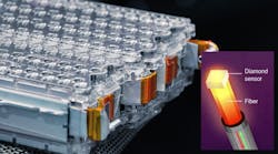
At the heart of the sensing system is a diamond nitrogen-vacancy (NV) center that offers high sensitivity over the sub-nanotesla (nT) to pT span (remember, where’s there’s current flow, there‘s also a magnetic field) (Fig. 1). (A NV center is a natural defect in a diamond’s crystal structure that can be “exploited” for a variety of sensing modes and quantum effects; see Reference.)
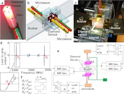
1. Prototype busbar current differential detection system: (a) 2 × 2 × 1 mm3 diamond sensor adhered to one end of a fiber. (b) Sensors A and B placed on both sides of the busbar for differential detection. (c) Photograph of sensors and busbar placed between a pair of magnets. (d) Optically detected magnetic resonance (ODMR) spectrum of the diamond sensor with the resonance frequency difference of the [111] NV− diamond, with high resonance frequency RH − low resonance frequency RL = 1050 MHz. S is illustrated as the slope of the ODMR at RL and RH. (e) Block diagram of the busbar current measurement system. The lock-in-amplifier output difference Y-X is integrated to control the two microwave generator frequencies to trace the low and high resonance frequency. (f) Time-division microwave frequency modulation for a lock-in-amplifier to reflect the magnetic field as its differential output. Four frequencies RL ± deviation depth frequency FDEV and RH ± FDEV generated by ± FDEV are provided within one cycle of modulation frequency FMOD without overlapping.
To detect 10 mA over a range of several hundred amperes, and do so accurately in a noisy automobile environment, the design used differential detection via two diamond sensors—one on each side of the busbar to eliminate in-vehicle common-mode environmental noise. Each sensor head consisted of a 2- × 2- × 1-mm diamond sensor adhered to one end of an optical fiber. The 19-mT static magnetic field needed for biasing was provided by the neodymium magnet.
The change in resonance is proportional to the current value. The team used a mixed analog-digital control of the frequencies generated by two microwave generators to trace the magnetic-resonance frequencies of the quantum sensor over a bandwidth of 1 GHz. This allowed for a large dynamic range (ratio of largest to smallest current detected) of ±1000 A. They also verified performance over a wide operating temperature range of −40 to +85°C.
Tests and Performance
Among their many tests, the team used a current pulse train from an external current source with an amplitude of 1 mA to 100 mA to confirm that a reading with accuracy of 10 mA can be detected in the time domain in a noisy environment.
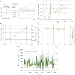
They also evaluated this prototype for Worldwide Harmonized Light Vehicles Test Cycle (WLTC) driving, which defines a standard test for energy consumption in EVs, among many other tests (see References). The sensor accurately traced the charge/discharge current from −50 to 130 A and demonstrated the battery-charge estimation accuracy within 1% (Fig. 2).
2. Battery-module current measurement: (a) Principle of mixed analog-digital control for the microwave generator frequency to trace the resonance frequency over a wide dynamic range. On the left, half of the ODMR “slope width” around the resonance frequency R in the spectrum is illustrated. On the right is the example microwave generator frequency control. It consists of analog control from the integrator feedback from the lock-in-amplifier and the digital control of the microwave generator center frequency to keep the analog control less than half of the ODMR “slope width” when the magnetic field change is larger than half of the ODMR “slope width.” (b) (Resonance frequency difference of sensor B, RFD_B)—(that of sensor A, RFD_A) when the busbar current of 10 mA to 130 A is supplied from the battery module. Owing to the limited accuracy in the reproducible current source controlling the battery module, the linearity is limited for less than 1 A. (c) The ratio of (RFD_B − RFD_A) to the busbar current as the busbar current changes from 100 mA to 130 A. ±0.5% linearity is confirmed from 1 to 130 A. (d) The fluctuation of (RFD_B − RFD_A) as the busbar current changes from 10 mA to 130 A. The left vertical axis is the magnetic field scaled with the gyromagnetic ratio 2γ = 56 kHz/μT and the right vertical axis is the current scaled with the ratio of (RFD_B0 − RFD_A0)/IB0 (1.78 MHz/A), where (RFD_B0 − RFD_A0) is (RFD_B − RFD_A) at IB0 = 130 A. The fluctuation is below 0.3 μT/√Hz or 8 mA/√Hz. (e) Measured (RFD_B − RFD_A) in thick green line when WLTC current pattern is supplied to the busbar. Using the ratio 1.78 MHz/A, (RFD_B − RFD_A) coincided with the whole WLTC pattern of IB in black line.
Finally, they used a current of ± 1000 A stepped at 20 A/step at a 2 sec/step rate, with comparable results. There’s non-common-mode noise that can’t be eliminated by the differential detection, noted the researchers. The actual noise level around the battery module in the automobile is estimated to attain 50 μT.
This is obviously a complicated scheme from both an advanced-physics perspective as well as actual implementation. It’s described in full detail in their paper “High-precision robust monitoring of charge/discharge current over a wide dynamic range for electric vehicle batteries using diamond quantum sensors” published in Nature Scientific Reports.
Will we see this sensor in cars? All I can say is “never say never.” Even a few decades ago, who would have foreseen that cars would be equipped with so many processors plus an array of sophisticated sensors including IC accelerometers, gyroscopes, radar, and cameras, plus voltage, current, pressure, and temperature sensors, to cite just a few examples. Of course, this unique sensing arrangement with its wide range and high resolution also could find a role in non-automotive situations.
References
Wikipedia, “Nitrogen-vacancy center”
Wikipedia, “Worldwide Harmonised Light Vehicles Test Procedure”


