Soul of a Blue Machine: The Engineering Behind Tek’s New 7 Series Oscilloscope
What you’ll learn:
- Tek’s new 7 Series scope features 125-GSPS rate, four channels, and 25 GHz of bandwidth, delivering high SNR and high ENOB to enable precise waveform capture and analysis.
- An extended look into the machine architecture and the engineering and design details in the machine.
- Specifications are available for download after the article.
It’s been about seven years since Tektronix announced a new high-end oscilloscope and its new 7 Series doesn’t disappoint. In fact, its capability leads me to coin the term, “fractional terasample scope,” which brings a new level to the game of test and measurement instrumentation.
The scope is well-suited for high speed communications link development and characterization, physics experiments, RF design, datalink characterization and conformance testing, signal integrity, and as a sixth sense for unlocking the secrets of Creation and the Universe.
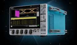
Tek’s 7 Series (Fig. 1) features a sample rate of up to 125 Gsamples/s (GSPS), 1/8 of a terasample per second; flat frequency response up to 25 GHz of bandwidth, up to four signal input channels with up to 5 V of input compliance, and very high equivalent number of bits (ENOB) and signal-to-noise ratio (SNR).
This fractional-terasample bandwidth wunderscope is impressive (more on its exceptional specs and features later). But it’s the underlying, bleeding-edge, engineering and craftsmanship in this machine that deserves marquee placement in any review.
Thermal Design
Exactly 70 years ago, Electronic Design covered the design engineering challenges that were solved by Tektronix engineers in “Design Forum: Compact Oscilloscope” (September 1955, Electronic Design magazine). Specifications for the Tektronix 310 oscilloscope shown on those pages called for an instrument weighing about 20 lb. and occupying about 3/4 cubic foot.
Planned for field use, it had to have performance comparable to that of laboratory oscilloscopes. Interestingly, the first PCBs designed at Tektronix were used in this 310 oscilloscope, with two double-sided, paper phenolic designs.
Back then fan speed was determined by line frequency, and the instrument was expected to operate at mains frequencies ranging from 60 (strangely enough 50 Hz wasn’t considered) to 800 cycles per second (hertz) So, use of a fan wasn’t in the cards.
To meet the sweep speed and bandwidth requirements, power dissipation requirements were estimated at around 200 W (actual production spec from the 310 manual is 175 W), primarily being dissipated by at least 30 to 35 vacuum tubes, five or six selenium rectifier assemblies, a bulky power transformer, and several filter capacitors.
By constructing a mockup of the case (similar to what was done with the 200 series) and using resistors as power sources, with thermocouples used for temperature characterization, Tek’s design team was able to arrive at a suitable thermal design that combined the chimney effect and perforations to arrive at the final packaging. The article on the Tek 310’s thermal design can be found on page 38 of the September 1955 edition of Electronic Design, here in the attached PDF:
Tek’s new 7 Series faced similar cooling challenges, but it uses components that don’t inherently heat metal to glowing temperatures to amplify signals. Thus, junction temperatures needed to be kept reasonably low and stable to maintain optimal performance.
The 7 Series’ designers faced a significantly higher power level, on the order of 1,500 W, primarily from the high-speed, silicon-germanium (SiGe), front-end ASICs, up to four of the largest FPGAs Altera had on offer at an estimated 140 W apiece, as well as both NVIDIA and AMD processors.
With knowledge that a “farm” of these machines could be mounted in racks for high-channel-count applications like physics experiments, the engineering team decided that forced-air cooling would be needed. They were clever in realizing that it’s air mass that cools a heatsink, not the velocity of air that’s usually used to create larger mass air flow that sounds like a hovercraft on departure.
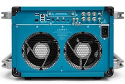
All of the high-powered semiconductors had massive conductive heat spreaders, which were then finned to couple them to flowing air mass. The cooling path was designed for cooling air to enter the bottom, and the forward sides, of the machine and to exit the back where two 8-in. fans moved the air mass (Fig. 2).
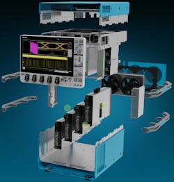
The design strategy worked nicely. The machine is extremely quiet when running, and the exhaust air is slightly warm, not hot to an inquisitive editor’s hand, because of the low heat flux due to the much larger swept area of the fan.
Mechanical Machinations
The box is fairly large at 12.85 × 22.1 × 17.9 in. ( 326.4 × 560 × 454 mm) and weighs about 83.7 lbs. (38 kg), depending on configuration. Its weight and size necessitated the installation of “pallbearer” handles to enable two people to lift the scope and move it safely and without injury. Being able to “bench” a 7 Series will likely be the latest engineering flex at gyms. The bottom and side air intakes and rear exhaust also work nicely with this handle setup.
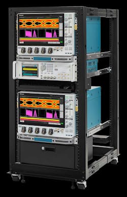
A rackmount kit is available for the 7 Series (Fig. 3), as well as a “flip kit” that enables a bottom-facing-bottom mounting of two machines in a rack. This places up to eight channels of inputs close to a circuit or system that’s near the vertical midplane of the two machines.
Creating a Bazillion-Input Oscilloscope System
The rackmounting capability facilitates dozens of machines to be configured for multichannel testing/monitoring. It’s very similar to the setups Tek had decades ago in Nevada during nuclear testing: An array of over a hundred scopes with film cameras on their screens (Fig. 4) awaited a trigger signal from the detonation to record the single-pulse event displayed on the scope screens and captured by each scope’s film camera.
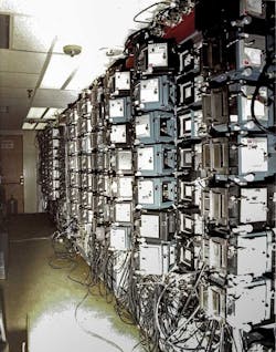
Word at the Tek museum is that the blast protection doors failed during one of the tests and Tek scored a second order for replacement of all scopes and cameras on site.
For modern-day large arrays of these data-acquisition and -processing machines, Tek created a very-high-frequency acquisition synchronization system on the 7 Series, whereby data sampling has time coherence and minimized latency with respect to a trigger event.
The capability can be seen on the back of the machine (Fig. 5). It uses the sync in, sync out, sample clock in, and sample clock out connectors. Though Electronic Design was briefed on the capability, and it’s real and engineered, the details likely crossed over the proprietary line in unfettered engineer-to-engineer discussions.
It’s probably best to contact Tektronix for more details on the interesting ability to create a dozens-of-channels sampling system for physics experiments, subatomic particle research, instantaneous event recording, or other high-speed, multichannel fast risetime or short-duration event, or sensors/transducers capture.
Electrical Design of the Scope
The machine is based on a new frontplane architecture (Fig. 2, again) that uses the TCA292D TekConnect adapter, comprised of a 2.92-mm RF connector, on each channel. It can interface to user signal cables, fiber optics, etc. Each input adapter has its unique S11 and S22 parameters stored for signal path optimization in subsequent signal processing.
In addition to the through screw-machined adapter, Tek also offers probes that can plug into each channel position in the frontplane.
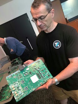
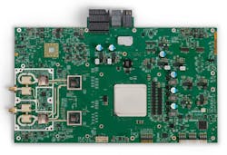
Behind the scenes, semi-rigid coax routes each of these frontplane inputs to one of the four possible acquisition boards, which are the on-end, shielded, boxes seen in Figure 2. Housed in each of those boxes is a data acquisition board (Fig. 6).
Up to two of the frontplane adapters can connect to up to two 2.92-mm RF input channels’ connectors via a semi-rigid coax cable.
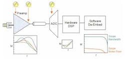
Using the upper input channel in Figure 6 as an example, a controlled impedance transmission line connects to the beige-colored input multiplexers. It can then connect to any calibration “input” source comprising a DAC and amplifier, or an RF oscillator, or to one of the two Tek085 amplifier/equalizer chips just to the right.
The SiGe-based Tek085 ASIC was designed specifically for the 7 Series. It boosts the input signal without excessively boosting the noise floor and flattens frequency response prior to digitizing the input signal.
“The low noise floor is a defining differentiator—and we built custom ASICs to achieve it. Designing them was one of the toughest lifts of the program. Over five years of close customer collaboration, we engineered the signal path end-to-end. The result speaks for itself: we didn’t just meet today’s performance targets, we set a new bar and built the foundation that will support future generations, delivering unprecedented speed, precision, and flexibility.” — Forrest Edwards, Program Manager & Principal Engineer
Each Tek085 preamp produces three output signal paths, one to each of the two adjacent Tek079 10-bit, 62.5-GSPS ADC chips.
The ability to tune and change filtering and power supplies (Fig. 7) creates a capability Tek calls “QuietChannel Technology.” Here, signals are boosted without increasing scope noise by utilizing active continuous time linear equalizer (CTLE) capability.
Each of the two Tek085 ADC chips, also using SiGe, performs 10-bit analog-to-digital conversion, has some signal shaping and filtering, and outputs 28 lanes per channel at a 24-Gb/s-per-lane rate to the humongous shiny thing just to the right of the board midline—the largest Altera Stratix 10.
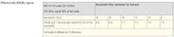
Other features enabled by the FPGA include 2 Gsamples of high-bandwidth memory (HBM) storage per channel, a slug of SerDes channels, and buckets of DSP resources to provide a complete analog and digital signal chain with a flat frequency response. In addition, the scope maintains a suppressed noise floor, a bandwidth rolloff of 27.5 GHz, and what Tek claims is the best ENOB in the business (Table 1) that was available at the time the 7 Series hardware design was more or less solidified.
Two weeks before the board layout was to be sent out as its final revision, the design of the acquisition board in Figure 6 would need changes. A large, highly desirable customer required additional functionality that, at the time, the 7 Series didn’t have.
The 7 Series was initially defined as a high-speed scope for capturing high-speed data streams, and it was specified to be triggered digitally. This digital triggering was fine for protocol analysis and looking at signal integrity, but it had excessive latency to perform single-event triggering, “like from a detonation.”
The brilliance, resilience, and resourcefulness of the engineering team looked to use an existing, low-latency, analog trigger ASIC from a higher bandwidth product, the Tek046 Trigger Chip, and fed it with the third output of the Tek085 preamp. It can be seen in the upper left of Figure 8.
The Tek046 also brought in some additional RF amplification that enabled future awesomeness with the 7 Series.
“From an engineering management perspective, the hardest part was achieving alignment as the target moved. When the goalposts shifted, we didn’t compromise — we re-engineered. Midway, a must-have customer request led us to rework the triggering architecture, leveraging proven silicon from our performance portfolio to add parallel analog triggering alongside the digital path. As a side benefit, we gained additional RF amplifiers for future high-speed serial triggering. The result: the 7 Series hits today’s targets, fulfills the original vision, and is ready for what’s next — a testament to our tightly integrated engineering teams and our focus on delivering a truly cutting-edge product.” —Gene Markozen, Senior Hardware Engineer
Another clever aspect of the board design lies in the pins at the bottom right corner of the acquisition board. These are the control signals for programming the FPGA with the machine fully assembled. Cutouts in the bottom of development machines would allow for programming access during development and manufacturing test. Those machines would be upside down in the development lab, not to mention the upside-down mode in a rack for minimizing proximity to a device under test (DUT).
"The 7 Series was built around customer workflows — from ease of use and UI to its packaging. Because an instrument like this is a major investment, we ensured customers can reuse probes they already own, even when that required extra software work. We added features like a flippable display in the Windows version (enabling upside-down operation), a quiet cooling system with a low-volume, pleasant-sounding fan, and a 15.6-in. 1080p display for high-resolution viewing of large datasets. We also designed a custom rackmount kit and a custom hard-shell transit case to simplify shipping with major shipping carriers. Every detail was designed with customers in mind.” — Tim Bieber, Principal Product Planner
Just above the programming pins is the 3-phase 100-A(!) power supply for the Stratix 10. Recall there can be up to four of these acquisition boards in each scope. For a spit-take, go look up the pricing on the largest Altera Stratix 10 devices…
And, finally, all of this signal data stuff has got to go somewhere, so the connectors at the top connect to a “topplane,” which is the horizontal board at the top of the machine in Figure 9.
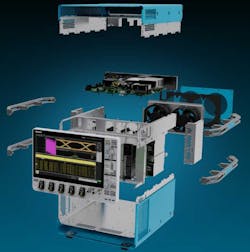
The topplane isn’t just a backplane for up to four data-acquisition boards to plug into. Rather, it’s a motherboard that houses some pretty impressive processing cajónes. An AMD Epyc PE3351 “Snowy Owl” processor fronts the machine, running an interchangeable choice of a Windows 10 or Linux OS (by swapping the disks shown in Figure 1 into the back of the machine), and a NVIDIA T1000 provides 890 Cuda cores for number crunching.
Low noise and moving data through the product quickly were major 7 Series objectives, so a native 10G Ethernet port moves data on and off the machine quickly, in either an electrical or SFP+ optical interconnect. There’s still USB on the machine for us old-timers.
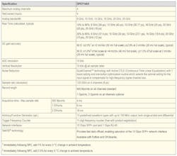
An ovenized oscillator provides a precise, stable, and low jitter (Table 2) timebase for the machine, and an Altera FPGA performs miscellaneous processing. To keep the data-hungry GPU fed, there’s a 4x PCIe switch that ups the lane widths to x16.

Essential Software
The software running the 7 Series comes from a legacy of code dating back to Tek’s 5 and 6 series of instruments. With the GPU, the software needed to be “refactored” to suit the platform’s new hardware and then regression tested on older series scope platforms to ensure the common software platform wasn’t broken on the earlier machines — nowadays going all the way back to the 2-series.
What that means is the features and operation of Tek’s machines share a common DNA, where upgrading scopes doesn’t necessarily mean the users need to relearn how to use them. The development of a suite of proprietary benchmarks would ensure that performance wasn’t degraded in any of the instrument series as new software was released.
“Building out the software for the 7 Series meant leveraging an existing software platform while making it work seamlessly with a completely different hardware architecture. We had to carefully balance sustaining support for existing products and meeting aggressive timelines, all while refactoring the software platform to support the 7 Series and scale for future hardware platforms.” — Jenny Yang, Software Engineering Manager
Manufacturing Includes Rigorous Testing
The days of tuning and aligning variable caps and RF inductors are gone. There are lots of virtual knobs to turn in the preamp, ASIC, FPGA, etc., to optimize each 7 Series for bandwidth, frequency response, S-parameter performance, and to meet the pages and pages of datasheet specs, available below.
Hours upon hours of calibration and test are spent on every machine, on the factory floor in Beaverton Oregon. Problems with the stringent RF performance found in contract-manufactured prototypes caused manufacturing to be brought in house. Yes, the 7 Series is made in America, by craftspeople with a company culture that goes back to just after World War II.
The rigorous burn-in, power-cycling testing, and the hours spent in assembly and test are as, or more, rigorous than seen and experienced in high-reliability central office (telecommunications) systems. We’re not going to disclose the details we’d seen, but the rigor and time spent on test and calibration is awe-inspiring and seems to go way beyond due diligence.
“From standards definition to board assembly, we designed tests to catch issues early and worked closely with engineering throughout the multi-year design and production of the 7 Series. Manufacturing was closely monitored at our Beaverton, Oregon campus, ensuring no barriers between teams. It was a true embodiment of cross-functional collaboration, with every group fully aligned to deliver a product that meets the highest standards.” - Jeff Schuh, Test Engineer
Spec Highlights
There simply isn’t enough space to cover all of the specifications of this oscilloscope series, so here are but a few samplings in Table 3. The rest of the specs can be found in the datasheet, attached here:
Budgetary pricing for Tek’s 7 Series starts at $165,000.
For more information on Tek’s 7 Series oscilloscopes, visit Tek's website.
Acknowledgements
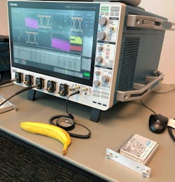
Thanks to the "Lady on TV” (Fig. 10) and her colleague at Publitek for herding the cats, getting pics and notes for me, and for keeping my banana sneak-pic a secret — all of which made this article possible. I’m also immensely grateful to the Tek team for spending their entire afternoon with me in casual, candid, deep technical, manufacturing, and business conversation, as well as for sharing their stories about the development and features of this new instrument.
Also, thanks to Dave Brown at the Vintage Tek Museum for the tour. It helped set the context for that day and inspired me to write about the 7 Series and the people and design behind its creation, much like Tracy Kidder did in The Soul of a New Machine (a great book), versus just waxing poetic about machine specs. -andyt
Andy's Nonlinearities blog arrives the first and third Tuesday of every month. To make sure you don't miss the latest edition, new articles, or breaking news coverage, please subscribe to our Electronic Design Today newsletter. Please also subscribe to Andy’s Automotive Electronics bi-weekly newsletter.
About the Author

Andy Turudic
Technology Editor, Electronic Design
Andy Turudic is a Technology Editor for Electronic Design Magazine, primarily covering Analog and Mixed-Signal circuits and devices and also is Editor of ED's bi-weekly Automotive Electronics newsletter.
He holds a Bachelor's in EE from the University of Windsor (Ontario Canada) and has been involved in electronics, semiconductors, and gearhead stuff, for a bit over a half century. Andy also enjoys teaching his engineerlings at Portland Community College as a part-time professor in their EET program.
"AndyT" brings his multidisciplinary engineering experience from companies that include National Semiconductor (now Texas Instruments), Altera (Intel), Agere, Zarlink, TriQuint,(now Qorvo), SW Bell (managing a research team at Bellcore, Bell Labs and Rockwell Science Center), Bell-Northern Research, and Northern Telecom.
After hours, when he's not working on the latest invention to add to his portfolio of 16 issued US patents, or on his DARPA Challenge drone entry, he's lending advice and experience to the electric vehicle conversion community from his mountain lair in the Pacific Northwet[sic].
AndyT's engineering blog, "Nonlinearities," publishes the 1st and 3rd Tuesday of each month. Andy's OpEd may appear at other times, with fair warning given by the Vu meter pic. His cartoon series, "Inventors", appears each week in Electronic Design Weekly.
Comment About the Article
To join the conversation, and become an exclusive member of Electronic Design, create an account today!

Leaders relevant to this article: