Bridging Microcontrollers and High-Speed RF Instrumentation
What you'll learn:
- How microcontrollers and single-board computers coordinate high-speed RF acquisition and generation.
- How SCPI and UART commands let simple controllers use advanced measurements without FPGA programming.
- How the hybrid model applies to predictive maintenance, automated testing, and research-grade radar nodes.

High-speed RF acquisition and generation was once firmly in the domain of lab equipment and specialized FPGA platforms. But modern workflows increasingly demand ways to integrate RF measurements into embedded prototypes, test rigs, and field systems built around microcontrollers. Developers want the simplicity of Arduino-class platforms while still accessing instruments capable of MHz-range sampling, deterministic control, or waveform synthesis.
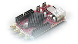
A growing set of open-source projects now bridge this gap by enabling microcontrollers and single-board computers (SBCs) to coordinate external RF front ends or software-defined instruments. In many cases, these projects pair MCUs with compact, network-controlled devices such as the Red Pitaya (Fig. 1).
To see how this works in practice, we’ll examine three distinct implementations that showcase this synergy:
- Predictive maintenance: Using a Red Pitaya and Arduino UNO to monitor the health of centrifugal pumps via high-speed vibration analysis.
- Industrial UART control: Creating a streamlined automated test environment where an Arduino or Arduino Opta commands high-speed measurements over a simple serial interface.
- PiRadar: A research-grade ionosphere imaging system that combines Raspberry Pi data handling with Red Pitaya high-frequency RF capabilities.
By bringing high-speed signal workflows into these familiar development environments, engineers can build sophisticated, field-ready instruments without the complexity of traditional benchtop setups.
Why is This Shift Happening?
Microcontrollers have become the default control layer for early prototyping, education, and automation. But they can’t natively sample or generate RF-range signals with sufficient resolution or bandwidth. Engineers typically solve this by connecting MCUs to specialized external hardware and programmatically controlling that hardware.
>>Download the PDF of this article

The pattern is the same across most projects: the MCU handles logic, scheduling, and integration; an external instrument handles the RF; and a simple command interface ties them together.
Approaches in Use Today
The same architecture appears across different projects: Red Pitaya handles the high-speed signal layer, while a microcontroller or SBC handles control, automation, communication, and system logic.
Project 1: Predictive maintenance of a centrifugal pump with Red Pitaya and Arduino UNO Q
In a predictive-maintenance setup, Red Pitaya acts as the high-speed vibration-measurement front end. An accelerometer mounted on the pump or motor housing provides the analog vibration signal. Red Pitaya captures and analyzes it for features such as RMS level, peak amplitude, and dominant frequency components.
Arduino UNO Q then uses those values for local decisions: comparing measurements with healthy or faulty patterns; logging trends; triggering warnings; reporting data over MQTT or CAN; and controlling relays, alarms, or status indicators. This is useful for faults such as bearing wear, misalignment, unbalance, and cavitation.
The key benefit is that Arduino doesn’t need to perform high-speed acquisition directly. Red Pitaya handles the signal fidelity, while Arduino turns the measurement into an industrial maintenance response.
Project 2: Industrial UART control between Arduino and Red Pitaya
A second approach is to use Arduino as a simple industrial controller for Red Pitaya over UART (Fig. 2). Arduino sends commands to generate a waveform, start an acquisition, or request a calculated result. Red Pitaya performs the high-speed task and returns values such as RMS level, frequency, amplitude, phase, or spectral magnitude.

Arduino then decides what happens next: pass or fail a unit under test, switch a relay, change a pulse-width-modulation (PWM) output, log a warning, or forward the result to another controller.
A simplified flow could be:
- Arduino -> Red Pitaya: set generator frequency
- Arduino -> Red Pitaya: start measurement
- Red Pitaya -> Arduino: return RMS and frequency
- Arduino -> system output: pass, fail, alarm, or relay action
This keeps the interface simple while still giving the system access to high-speed measurement and generation. For a more industrial implementation, the same concept could be built around Arduino Opta or a similar industrial controller. In this case, Red Pitaya provides the measurement front end and Opta handles plant-facing I/O, relay outputs, machine-level logic, and integration with existing automation systems.
Project 3: PiRadar with Raspberry Pi and Red Pitaya
PiRadar combines Raspberry Pi and Red Pitaya in a compact radar-node concept for ionosphere imaging. Red Pitaya handles RF acquisition and generation through its fast analog inputs and outputs, while Raspberry Pi manages data handling, storage, processing, and remote communication.
In this setup (Fig. 3), Red Pitaya connects to the antenna-side signal path and performs the time-sensitive RF work. Raspberry Pi receives the data stream, stores or processes it, and can send it to a remote user. This shows the same split in a research-grade application: one device interacts with the high-speed physical signal, while the other coordinates the application around it.

Why the Hybrid Model Works: Efficiency Through Abstraction
The utility of these models lies in their ability to abstract complex physics into actionable data. Instead of forcing a developer to write low-level FPGA code, the system relies on these key technical pillars:
1. Command Abstraction (The How)
Standardized interfaces like SCPI (Standard Commands for Programmable Instruments) or REST APIs act as a translator.
- How it works: Rather than calculating a fast Fourier transform (FFT) on a microcontroller, which would overwhelm its processor, the MCU sends a simple text command over UART or Ethernet.
- The benefit: The Red Pitaya performs the heavy math internally and returns a single numeric value. This allows an Arduino UNO, which typically struggles with MHz-range data, to "see" high-frequency signals as simple variables.
2. Deterministic Performance in the Field (The Why)
The proof of this model is found in how it solves the bottleneck of real-time response.
- Example from Project 1: In the centrifugal pump setup, if the system relied on the Arduino to sample vibration at 100 kSPS, the controller would have no cycles left to manage the MQTT heartbeat or safety relays. By using Red Pitaya as a high-speed buffer, the Arduino Opta or UNO remains fully available for plant-facing logic.
- Example from Project 3: In the PiRadar application, the Raspberry Pi provides the high-level UI and networking, but it can’t guarantee the nanosecond-precision timing required for RF pulse generation. The hybrid model provides the proof that you can achieve research-grade RF synchronization while still using a Linux-based SBC for data storage and remote access.
3. Rapid Portability and Scale
Because the control logic is decoupled from the signal acquisition, this model offers a unique plug-and-play flexibility for testing. An engineer can develop a test script on a PC using Python, then move that exact same logic to a microcontroller for a permanent field installation. This lowers the learning barrier from months of FPGA training to a few days of standard embedded programming, making it a game-changer for both low-cost teaching labs and rapid industrial prototyping.
Where the Ecosystem is Heading
As open-source libraries and tooling mature, developers are gaining more reliable ways to combine deterministic MCU control loops with high-speed external digitizers. It’s becoming increasingly feasible to automate RF test routines directly from embedded firmware, reducing the need for large external rigs. Low-cost SBCs can now function as fully scriptable measurement nodes, orchestrating complex sequences that once required lab-grade setups.
These capabilities make it possible to build repeatable, software-defined test flows without dedicated test equipment or proprietary toolchains. Together, these trends reduce the gap between initial bench prototypes and systems that are ready for deployment in industrial, academic, or field environments.
From Lab Bench to Field Implementation
The convergence of microcontrollers and RF hardware is more than a convenience — it’s a shift toward decentralized, high-performance measurement. By offloading the heavy lifting of signal processing to dedicated FPGA-based front ends, developers are no longer restricted by the clock speeds of their primary controllers.
The impact of this modular approach is best seen in the results of the projects discussed:
- Industrial maintenance: The hybrid model transforms a standard Arduino into a sophisticated diagnostic tool. By using the Red Pitaya to process high-speed vibrations, engineers have successfully identified pump cavitation and bearing wear before catastrophic failure occurred, achieving industrial-grade monitoring at a fraction of the cost of traditional PLC-integrated vibration modules.
- Automated testing: The use of UART-controlled instrumentation has streamlined production lines. Facilities can now deploy headless test rigs where a single Arduino Opta manages an entire rack of Red Pitayas, performing sub-microsecond timing measurements that previously required a dedicated PC and a rack of benchtop oscilloscopes.
- Global research: Projects like PiRadar prove that this architecture is robust enough for atmospheric science. By pairing the Raspberry Pi’s networking with the Red Pitaya’s RF agility, researchers can deploy low-cost, remote ionosphere imaging nodes in locations where shipping and maintaining traditional radar equipment would be logistically impossible.
This ecosystem of open-source libraries and standardized interfaces is maturing rapidly. As we’ve seen through these three applications, the barrier to MHz-range instrumentation is no longer a matter of mastering FPGA design or specialized hardware. Rather, it’s simply a matter of connecting the tools engineers already know to the hardware that handles the physics.
For the next generation of automation, sensing, and robotics, the hybrid model isn’t just an alternative — it’s the new standard for rapid, high-performance prototyping.
>>Download the PDF of this article
About the Author
Črt Valentinčič
CTO, Red Pitaya
Črt Valentinčič is the co-founder and CTO of Red Pitaya, where he has spent over a decade building powerful, accessible computing tools for engineers, researchers, and developers around the world.
Comment About the Article
To join the conversation, and become an exclusive member of Electronic Design, create an account today!

Leaders relevant to this article: