Members can download this article in PDF format.
A traction inverter manages the flow of energy from the high-voltage battery pack to the motor, which turns the wheels to propel the vehicle. Since all motors can be generators, it also handles power regeneration from braking. These two functions give it great influence over an electric vehicle’s (EV) range, performance, and driving experience.
To extend driving range and reduce motor size and weight without compromising the power level, a traction motor must be able to run at high speeds (>30,000 rpm). This, in turn, requires fast sensing and processing, as well as the efficient conversion of dc to ac voltages.
Sponsored Resources:
- Traction inverters: the driving force behind vehicle electrification
- Reducing power loss and thermal dissipation in SiC traction inverters
- 3 ways MCUs are addressing common design challenges of 800-V EV traction inverters
To achieve these goals, current traction-inverter design trends include employing SiC MOSFETs for the switching transistors in the power stage, using high-voltage 800-V batteries, and integrating multiple subsystems to obtain high power densities (a measure of how much power can be processed in a given space).
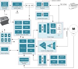
Simply put, a properly designed EV traction inverter can help extend driving range and enable faster motor speeds, higher efficiency, and a smaller system size (Fig. 1).
Wide-bandgap (WBG) switch and powertrain integration are among the key technologies supporting high-power-density inverter design. WBG technology such as silicon carbide (SiC) allows engineers to design higher-power systems in the same footprint with weight and gain efficiency across temperature, speed, and torque to increase the vehicle’s driving range.
Advancing Performance
Traction inverters have traditionally used insulated-gate bipolar transistors (IGBTs). But with the advancement of semiconductor technologies, SiC metal-oxide semiconductor field-effect transistors (MOSFETs) offer the ability to switch at higher frequencies than IGBTs. Thus, they improve efficiency through resistive- and switching-loss reductions while increasing power and current density. Moreover, SiC MOSFETs have lower switching losses, are smaller than IGBTs and run cooler, reducing weight, size and energy waste in the drive system.
The very fast switching capability of SiC transistors is part of their efficiency advantage. Moving to SiC switching, however, presents challenges. This high switching speed also creates the potential for high levels of electrical noise that could mistakenly activate a motor. And a SiC switch is more susceptible to damage from short circuits than IGBT technology.
To combat these shortcomings, the EV needs the right driver technology to accompany the move to SiCs. Gate drivers can control these risks with safety features that reduce the impact of noise in the drive system.
Although most EVs today use 400-V batteries, there’s a notable transition to 800-V architectures. A higher-voltage system makes it possible to use a lower current when charging the battery, which reduces overheating and allows for better power retention in the system. This power can be applied toward achieving a longer driving range.
An 800-V system also has the added advantage of reducing mass. Since the higher voltage enables the motors to run at speeds of 20,000 rpm, well over double that of a 400-V system, it improves power density.
MCUs and Fast Control Loops
Advances in traction inverters, enabled by microcontrollers with real-time control capabilities and isolated gate drivers, is another element pushing EV performance. An MCU with a fast control loop allows for the use of a high-speed, lighter motor as well as powertrain integration such as an inverter integrated with dc-dc converters. A fast control loop also helps to minimize torque ripple and provides smooth speed and torque current profiles to the traction motor.
Texas Instruments has a deep roster of MCUs and gate drivers featuring fast current loop control that can adjust the motor switching algorithm every one-millionth of a second when detecting a short to protect the switch from damage. A low-latency control loop also enables engineers to run the motor at a higher rpm, which can reduce both the size and weight of the motor.
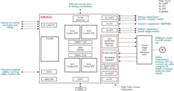
TI MCUs have traction inverter control-loop latency as low as 2.5 µs, with the new automotive quad-core Arm Cortex-R5F AM2634-Q1 demonstrating latency <4 µs (Fig. 2). These high-performance real-time control MCUs can help solve most common design challenges to achieve higher efficiency and greater performance in 800-V traction-inverter systems.
Gate Drivers
Driving SiC MOSFETs in an EV traction inverter, especially at power levels >100 kW and with 800-V buses, requires an isolated gate driver with reliable low- to high-voltage galvanic isolation technology, high drive strength, fault monitoring, and protection against various fault conditions. Protection includes fast overcurrent protection, short-circuit protection, isolated temperature and voltage sensing, and undervoltage lockout.
The traction inverter further monitors auxiliary circuits to prevent system-level failure modes such as over- and under-torque, unintentional motor commutation, or motor shutdown. Particularly for SiC MOSFETs, the gate-driver IC has to minimize switching and conduction losses that include turn-on and turn-off energy. With EV traction inverters increasing in power, choosing the right isolated gate driver can reduce SiC MOSFET power losses and enable faster switching frequencies and therefore higher efficiency.
Conclusion
Traction-inverter and motor-control systems are critical to enable optimal EV performance. Increasing the efficiency and robustness of the inverter boosts overall vehicle efficiency. To build the next generation of these systems, design engineers must reduce power losses and improve system efficiency to make EVs more reliable, increase driving range and enhance safety.
Every inverter supplier is working hard to improve EV performance. So why choose TI for traction inverter systems? Among the many reasons presented in this article, two at the top of the list are to achieve longer driving range and to create a better driving experience via a fast control loop that provides smooth speed and torque-current profiles to the traction motor.
What’s more, TI’s automotive microcontrollers and other components for traction inverters and motor control are functional-safety compliant. They can help system designers meet all safety-integrity levels up to ASIL D, which represents the strictest test of automotive safety.
Sponsored Resources:


