Members can download this article in PDF format.
Motors are proliferating in industrial environments, driving the demand for precise, compact motor-control designs. Real-time microcontroller units (MCUs) with hardware accelerators tailored for low-latency control-loop applications are enabling motor drives with high performance yet low cost per axis. Coupled with sensors and power-switching devices, including wide-bandgap versions, the MCUs are boosting the performance of factory-automation and related applications.
Industrial Drive Foundational Subsystems
An industrial drive system with real-time control includes three foundational subsystems that handle sensing, processing, and actuation. The subsystems combine to provide precise position control, speed control, or both.
In an elevator drive, for example, position control allows the elevator to stop at specific floors, and speed control minimizes the time to move from floor to floor while keeping acceleration and deceleration to comfortable levels. Similar considerations apply to motor drives for robotics, computer-numerical-control machines, and factory-automation equipment.
The sensing subsystem is key to achieving precise control. It generally provides angular motor-shaft position and speed sensing or linear conveyer position and speed sensing.
The sensors can take the form of incremental optical encoders with a few hundred to a thousand slots per revolution. They typically communicate using quadrature-encoded pulses (QEPs). Alternatives include significantly higher precision absolute encoders that have much higher slot counts per revolution.
Some absolute encoders transmit their measured values as a digital representation using standard protocols such as the T-format by Tamagawa or Bidirectional Serial Synchronous C (BiSS C) by iC-Haus GmbH. Others employ electromagnetic or resolver-like techniques and require accurate measurement of electrical sinusoidal signals.
The processing subsystem requires MCUs with high computational power to execute motion-control algorithms. Typically, the MCUs have 32-bit word lengths with 64-bit floating-point support and hardware accelerators to execute the necessary trigonometric, logarithmic, and exponential math. In addition, many MCUs for motor-drive applications have onboard analog comparators, QEP interfaces, analog-to-digital converters (ADCs), and pulse-width-modulated (PWM) outputs.
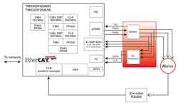
The system in Figure 1 leverages an MCU whose features include two trigonometry math units (TMUs), two control-law-accelerator (CLA) real-time coprocessors, a QEP interface, an EtherCAT (Ethernet for Control Automation Technology) interface, PWM outputs, a fast serial interface (FSI), and ADCs.
The actuation subsystem includes power devices and drivers that respond to the MCU’s PWM output. The drivers must deliver the necessary drive strength with minimal timing skew to turn the power devices on and off at the intended times. The drivers also may include current-sensing capabilities and implement overcurrent and overtemperature protection. The power devices themselves are increasingly based on wide-bandgap technologies to achieve fast switching speeds and low losses to enable fast control-loop speeds.
From FPGAs to MCUs
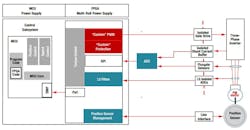
Commercial off-the-shelf (COTS) MCUs have long been a part of motor-drive applications, but many manufacturers traditionally added field-programmable gate arrays (FPGAs) to their systems to execute control functions beyond the MCUs’ capabilities. Consequently, designers built complex, expensive boards incorporating both an MCU and FPGA plus the multi-rail power supply required by the latter (Fig. 2).
Today, however, catalog MCUs can perform functions once reserved for FPGAs, resulting in simpler designs, lower costs, and board-space savings. This frees developers to focus on product differentiation as well as their core competencies—not FPGA design.
To help you effectively deploy COTS MCUs in your motor-drive designs, Texas Instruments offers its C2000 MCU DesignDRIVE platform and architecture. C2000 MCUs are available with a CLA real-time coprocessor and a TMU to speed up calculations that once required FPGAs. The MCUs can support 150-ps high-resolution PWM and perform angle calculations in as little as 70 ns. They also can execute a floating-point torque-loop calculation in 2.5 µs.
In addition to the MCU lineup, DesignDRIVE includes fast current loop (FCL) software that increases a motor drive’s response. TI provides FCL algorithms in the form of a linkable library that makes use of the MCU’s TMU and CLA parallel-processing core. FCL provides support for four high-speed 12- or 16-bit ADCs, enhanced PWM, and enhanced QEP or absolute encoder feedback.
DesignDRIVE also includes Position Manager technology, which integrates on-chip interfaces to industry-leading analog and digital position sensors, eliminating the need for expensive resolver-to-digital chipsets or other external sensor-interfacing components. In addition to reducing development time, Position Manager technology—tested across a variety of sensors—also minimizes the required compliance and interoperability testing undertaken by system manufacturers.
Finally, DesignDRIVE includes support for EtherCAT to help manage communications. The EtherCAT support includes a demonstration project that lets you evaluate the transfer latency from an external EtherCAT controller to a C2000 MCU, and it helps you determine the required processing bandwidth and hardware-extraction-layer memory footprint.
Reference Design and Development Board
To help get you started, TI offers the TIDM-02006 distributed multi-axis servo-drive reference design using C2000 real-time MCUs. Each C2000 TMS320F280049 or TMS320F280025 MCU controls a distributed axis, running a motor-current control loop.
A single TMS320F28388D MCU, leveraging its multiple cores, runs position- and speed-control loops for up to 16 axes. The same F2838x also manages EtherCAT communications with a host computer. An FSI with skew compensation transfers speed, position, current, and command information among distributed, decentralized controllers. An integrated software frequency-response analyzer (SFRA) supports online speed- and current-loop tuning of any digitally controlled closed-loop system.
To complement the reference design, TI offers development boards, including the LAUNCHXL-F280049C, which features a 100-MHz TMS320F280049C controller and FSI connector (Fig. 3).
Conclusion
Real-time MCUs are implementing streamlined, low-latency architectures that provide high performance to deterministically execute the motor-control functions once relegated to FPGAs. They incorporate advanced hardware-based engines that accelerate compute-intensive tasks.
TI’s C2000 family maintains pin and software compatibility across devices to simplify design migration and support code reuse. On top of that, the company offers reference designs and development boards to help get you started on your motor-drive designs.


