Improve Liquid Handling with These Motion Techniques

Liquid-handling systems often use peristaltic pumps to perform critical operations. Examples of applications and the functions performed by peristaltic pumps include:
- Infusion pumps: Administer medications, nutrients, and fluids intravenously in a controlled manner.
- Dialysis machines: Circulate blood and dialysate during hemodialysis.
- Heart-lung machines: Circulate blood in cardiopulmonary bypass procedures during heart surgery.
- Laboratory applications: Transfer fluids for testing and research, such as in auto analyzers and cell media harvesting.
- Negative pressure wound therapy: Employed in systems that use negative pressure for wound healing.
- Chemotherapy and infusion therapies: Precisely deliver chemotherapy drugs and other infusion therapies.
- Automated liquid handling: Used in automated systems for dispensing reagents and samples in clinical diagnostics.
- Nutrient and fluid delivery in neonatal care: Provide controlled feeding and hydration for premature infants.
An important advantage of peristaltic pumps is that the transported liquid is isolated from the pumping mechanism, which reduces the chance of contamination. However, peristaltic pumps exhibit a pulsating flow behavior due to how the roller-wheels engage with the liquid tubing. Fortunately, these fluctuations are predictable allowing adaptive techniques to be deployed.
In this article, we examine these phenomena in more detail and demonstrate how high pumping accuracies are achievable with the use of an adaptive control method.
Peristaltic Pumps and More
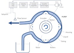
Peristaltic pumps are commonly used to deliver larger amounts of liquid to a site that requires such liquid. A typical peristaltic pump consists of a pump housing, a spinning rotor driven by a motor/encoder, typically three or four rollers, and a flexible section of tubing. The rollers compress the tubing while rotating, thereby moving pockets of liquid from intake to outlet.
The advantage of peristaltic pumps is that only the tubing comes in contact with the liquid. The disadvantage is that the discrete pockets create an unsteady flow rate, resulting in difficulty delivering small, precise volumes of liquid. Higher-end peristaltic pumps typically use a brushless DC (BLDC) motor with a quadrature encoder and Hall sensors. A BLDC motor/encoder lends itself well for a more sophisticated controls approach (Fig. 1).
Figures 2 through 4 illustrate several methods of controlling the pump motor in a peristaltic pump. The simplest controller (Fig. 2) applies a voltage to the motor without any form of feedback. The motor speed will depend on the applied voltage.
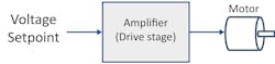
Clearly this control gives no consideration to the actual delivery velocity of liquid or the velocity of the motor due to the tubing compression. Thus, it will result in the largest flow variations. In addition, stopping the pump is imprecise, leading to an unpredictable amount of liquid being delivered. For large volumes of liquid, it may not matter since many pump rotations are involved. However, for smaller volumes, this effect becomes important.
>>Download the PDF of this article
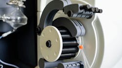
Figure 3 demonstrates a control mode wherein encoder signals are fed back to a velocity control loop that’s regulated by a velocity setpoint and Hall signals are fed back to a current control loop. The velocity loop outputs a torque command to a current loop (proportional-integral, or PI, controller) and a field-oriented control (FOC) scheme that generates a pulse-width-modulation (PWM) signal as an input to the amplifier.
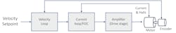
When one of the rollers starts compressing the tubing (or starts releasing it), the velocity changes and the torque delivered by the motor is changed as well, resulting in a more even rotor rotation. Depending on the “stiffness” of the controller, this will result in a fairly even velocity of the rotor and, thus, in even liquid delivery.
Figure 4 is an enhanced version of the controller in Figure 3, wherein a flow compensation loop is added to the control scheme. This results in a system in which the increases and decreases in flow from the rollers compressing the tubing is part of the feedback in the control system. Consequently, it makes the system stiffer than the controller in Figure 3, which isn’t aware of the actual flow-rate changes.

However, in such a system, the reaction speed of the flow sensor must be faster than the actual changes in flow. It can be accomplished with turbine-based sensors as well as non-contact sensors such as ultrasonic sensors. This controller, by measuring the actual flow rate, gives a more robust compensation mechanism particularly at low velocities.
Selecting the Motor Type
Figure 5 shows some general performance characteristics for BLDC, DC servo, and stepper motors. BLDC motors typically provide the highest figures of merit for power output to weight, which can be important for mobile pumping applications. DC brush motors under servo control can also be employed in the peristaltic pump application. However, their big disadvantage is the use of mechanical brushes for commutation. These brushes can wear or begin to deliver uneven torque as they age.
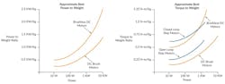
Stepper motors are also a candidate for this application, especially if a control technique called closed-loop stepper is applied. This technique uses an encoder to operate the step motor as a two-phase BLDC motor. The result is significantly higher torque over the operating range of the motor thanks to the elimination of mid-range instability, a torque killer for open-loop step motors.
Despite these choices in motor type, the most popular choice for the peristaltic pump motor type is BLDC motors. Brushless motors with high-resolution encoders driven by a position servo loop can achieve very high accuracy and react extremely quickly to the changes in load that are inherent in peristaltic pump operation.
Either geared or direct-drive BLDC motors can be employed, but direct drive is increasingly preferred because it avoids compliance and backlash, which are inherent to use of a gearhead. Direct drive means the brushless motor will be able to follow the commanded position or velocity profile very accurately.
A key control technique for direct-drive BLDC motors is sinusoidal (also known as encoder-based) commutation. The standard method of commutating brushless motors uses Hall sensors and defines six commutation states, one per 60 electrical degree interval. These square-wave drive waveforms can result in torque output discontinuities.
Encoder-based commutation is able to define many more than six states, which allows sinusoidal waveforms to drive the BLDC motor phases. The result is more accurate torque output and improved rotational smoothness.
Pump Implementation Details
In our experiments, we used an FPU 500 pump from Omega coupled with a BLDC motor incorporating Hall sensors and a 2,000-count (500 line) quadrature encoder. The controls were provided by a Performance Motion Devices Juno MC78113 Developer Kit board with onboard amplifier. The Juno IC was running a current loop (PI) at 20 kHz and a velocity loop at 200 Hz (when used).
A McMillan model S-111 flow meter with a range from 13 to 100 milliliters per minute (mLPM), 1.0% accuracy, 0.2% repeatability, and less than one second response time (full scale) was used for the controller in Figure 4.
Operating the pump with 4-mm tubing, we were able to easily achieve a flow rate of 20 mLPM (20% of full scale) at a rotation speed of 0.5 rps or 30 rpm. Since the Omega pump employs three rollers spaced at 120 degrees, we see that a roller transfers along the sidewall of the pump housing in approximately 1.5 seconds.
For each of the three control schemes in Figures 2, 3 and 4, we measured actual flow as indicated by the S-111 sensor as well as the RMS and average motor torque. We then analyzed the dominant frequencies in the spectrum.
Figure 6 shows the measured output of the open-loop voltage mode measurements. Figure 6a depicts large variations in actual flow and Figure 6b shows that the dominant frequencies are around 0.5 and 2.1 Hz, corresponding to the motor rotation frequency and the roller rotation speed, respectively.
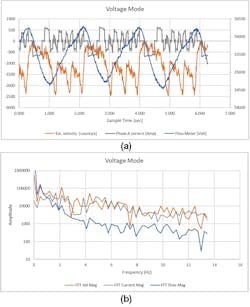
Figure 7 shows the same measurements for the velocity-loop mode in Figure 3. As can be seen from the figures, the variations in actual flow rate are significantly reduced. Most significantly, the motor frequency (0.5 Hz) is no longer showing in the flow signal, although the variations caused by the rollers (2 Hz) are still clearly visible.
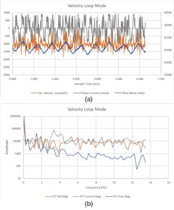
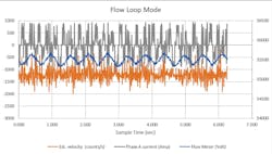
Figure 8 shows the results of the controller in Figure 4, which adds the outer control loop for flow to the velocity loop. As can be seen, the variations in flow are further reduced.
Conclusion
Figure 9 summarizes the above results and looks at the standard deviations of the measurements. As can be seen in the figure, the standard deviation in the actual flow was reduced from 513 to 90 mLPM — an improvement of more than 5X.

The control modes described in this article lend themselves well for low flow operation of peristaltic pumps if the controller adds at least a velocity/FOC loop. However, it can be improved even further with the addition of an outer control loop that integrates an actual flow sensor.
References
>>Download the PDF of this article
About the Author

Chuck Lewin
Chuck Lewin, Founder and CEO, Performance Motion Devices Inc.
Chuck Lewin is Founder and CEO of Performance Motion Devices Inc. In 1992, Lewin developed a motion control on an IC technology to found PMD. In less than a year, the company released its first IC multi-axis motion processor with functions previously only on board-level motion control products. In 2024, the company introduced its ION/CME N-Series PCB-mountable drive, delivering integrated motion control, network connectivity, and power amplification in a single module.
Today, the company manufactures motion controls for servo and step motors with CAN, serial, SPI, and Ethernet communications—and capable of S-curves, synchronized multi-axis contouring, precision torque control, field-oriented control, and many other advanced capabilities.
Comment About the Article
To join the conversation, and become an exclusive member of Electronic Design, create an account today!

Leaders relevant to this article: