How to Control Brushless Motors (Part 5): Choosing a Motor-Control IC
What you'll learn:
- Overview of the different components of brushless DC (BLDC) motor control from position control to PWM switching.
- Differences between torque, velocity, and position-control ICs for BLDC motors, and example products from PMD.
- The benefits of a fully integrated PCB- or module-based BLDC motor drive from mid-to-high power levels.
As outlined in the middle parts of this series, brushless DC (BLDC) motor control is typically split into several functions that must be carefully coordinated to maintain smooth, balanced, and efficient motion.
First, a position-control loop compares the desired motor position with the measured position. Using a predefined motion profile, it outputs a desired current command, which translates to the amount of torque required to move the motor into the target position. In other situations, velocity control rather than position control is required, in which case the BLDC motor controller uses a velocity servo loop rather than a position servo loop.
The system then commutates the current command by distributing it across the motor’s windings. Subsequently, a current-control loop measures the actual current flowing through each winding and adjusts the applied voltage to match the commanded current as closely as possible. Due to their very high efficiency and easy controllability, pulse-width-modulation (PWM) switching bridges are widely used to apply these voltages to the windings.
To conclude this series, we now turn to practical considerations for selecting a BLDC motor controller and how these different functions are split up in the first place. What follows are a few popular configurations. Depending on your system’s control requirements and preferred level of integration, at least one of these approaches is likely to be a match.
Approach #1: BLDC Motor-Control IC with Internal Amplifier
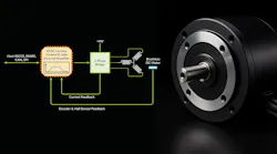
The first approach uses a low-cost motor-control IC with an internal amplifier (Fig. 1). This allows it to deliver voltage commands directly to each coil of the motor rather than require a separate PWM switching bridge to drive the motor windings. The host is typically a microcontroller (MCU), and commands are communicated to the motor-controller IC using an analog voltage, a digital signal over a Serial Peripheral Interface (SPI), or an asynchronous serial interface.
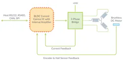
These solutions tend to support velocity-control functions such as sensorless control. However, they have several limitations, such as minimal current-drive levels (typically in the 1- to 4-A range) and the inability to handle more advanced current-control approaches.
Most of the offerings in this category are application-specific and dedicated to tasks like fan control. So, these types of fully integrated motor-control ICs are rarely used in general-purpose motion-control applications.
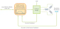
Approach #2: BLDC Motor Torque-Control IC
The second approach leverages a brushless motor torque-control IC (Fig. 2). These devices typically integrate commutation and current control, including the full signal chain from current-sense inputs to field-oriented control (FOC) algorithms and switching-bridge control.
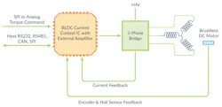
In these architectures, a digital or analog torque command is input from external circuitry or a host MCU. Some of the motor-control ICs in this category also provide a higher-level communication channel such as SPI, CAN, RS-232, or RS-485. This channel can be connected to a MCU or PC and is useful for collecting motion-trace information, which could be used to measure the motor’s performance and optimize the control settings of the motor-control IC.
>>Download the PDF of this article, and check out the rest of the parts to this series.
These BLDC motor-control ICs, e.g., PMD’s MC73112 and MC73112N ICs, can be used in a wide range of applications, including bottle-capping equipment, pump control, drone-propeller control, marine-propeller control, and robotic wheel control, among many others. These devices are also often employed within a larger control circuit that inputs encoder information, closes a position or velocity loop, and continually sends a torque command stream to the motor torque-control IC.
Approach #3: BLDC Motor Velocity-Control IC
This approach uses a brushless motor velocity-control IC (Fig. 3). These devices integrate a wide range of functions, including velocity profile generation, closed-loop velocity control, encoder or tachometer inputs, commutation, and current regulation. They typically support the full signal chain for current control, from current-sense signal input to FOC and switching-bridge control signal output.
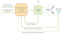
Such motor-control ICs — e.g., PMD’s MC73113 IC — operate on a similar principle as motor-torque control ICs. But instead of using torque commands from the host MCU or external circuitry, these devices take a velocity command as the input, either in digital or analog form. Alternatively, a high-level communication channel such as SPI, CAN, RS-232, or RS-485 can be used to send packets of commands that specify profile information.
In addition to commanded velocity profiles, this channel is useful for collecting motion trace information that analyzes the motor application performance and optimizes the control settings of the IC. The packets sent by the host encode commands have meanings such as "set the profile acceleration to 123,456” or “report the encoder position.” Packet commands set control parameters, execute profiles, query the status of the controller, and more.
Typical applications for BLDC motor velocity-control ICs include pump control, centrifuge control, spindle control, fan control, gate and door control, conveyer systems, packaging equipment, food processing equipment, and wheel control for mobile robots.
Approach #4: BLDC Motor Position-Control IC
The next approach involves a brushless motor position-control IC (Fig. 4). These devices integrate most of the core functions for high-performance position applications, including motion profile generation, closed-loop position control, encoder input, commutation, and current control.
As with motor torque-control and motor velocity-control ICs, they usually support everything from the current-sense signal input — in this case, analog input signals — to FOC and switching-bridge control signal output.
To control these devices, a communication channel such as SPI, CAN, RS-232, or RS-485 is used to send commands. Through the interface, the host MCU sends command packets that define motion behavior and query system status.
For example, commands can include "set the profile type to S-curve point-to-point” or “report the encoder position,” or “set the profile acceleration to 100.” These command packets are used to configure control parameters within the brushless motor-control IC, initiate and manage motion profiles, and monitor the status of the motor-control system.
A common variation of this architecture accepts a continuous external data stream of position command values. The data can be provided via an SPI interface or other interface, and it’s intended to be compatible with systems that use a central “master profile generator” commanding multiple axes simultaneously.
In contrast to BLDC motor-control ICs that support only torque or velocity control, position-control ICs often provide motion-peripheral support beyond standard quadrature encoders. This can include interfaces for BiSS-C digital serial encoders, analog sin/cos encoders, SPI-based encoders, and other formats that support both absolute and incremental position feedback. Several companies offer products in this category, including PMD with its MC53113 IC.
Typical applications for BLDC motor position-control ICs include laboratory automation, continuous contouring, packaging machinery, semiconductor capital equipment, robotics, centrifuge control, respirators, pick-and-place machines, packaging equipment, food-processing equipment, patient treatment devices, and more.
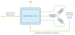
Approach #5: BLDC Motor-Control Drive
The final approach uses a PCB- or module-based brushless motor drive that provides everything from profile generation, position loop control, and encoder input to commutation, current control, and amplification (Fig. 5). Off-the-shelf BLDC motor drives come in many variations, ranging from simple brushless motor commutation and amplification devices to products that provide profile generation, data logging, overcurrent detection, and other drive safety features, as well as FOC.
These motor drives typically receive command packets specifying desired control settings and profiles from an external source. They’re further split into several other categories: tightly coupled systems, which receive a continuous stream of position or torque values from a master profile generator; and loosely coupled systems, which receive higher level commands commanding complete move profiles that are internally generated by the drive.
One popular alternative to these motor drives allows user application code or motion sequences to be downloaded into the drive and executed. These drives are sometimes referred to as intelligent BLDC drives or standalone BLDC drives.
Many BLDC motor-control drives offer motion peripheral support beyond quadrature encoders, such as BiSS-C digital serial encoders, analog sin/cos encoders, SPI bus encoders, and other encoders that support absolute as well as incremental position input. A large number of vendors offer these products, including PMD with its Atlas Amplifiers, ION 500/3000 Drives, and ION/CME N-Series Drives.
BLDC motor-control drives span a wide range of power drive capabilities, stretching from 100 W and below to 2.5 kW and above. Further variations of these BLDC motor-drive products interface to host controllers via network buses such as RS-485, CANbus, CANopen, Profibus, Profinet, DeviceNet, Ethernet, EtherNet/IP, and EtherCAT.
>>Download the PDF of this article, and check out the rest of the parts to this series.

About the Author

Chuck Lewin
Chuck Lewin, Founder and CEO, Performance Motion Devices Inc.
Chuck Lewin is Founder and CEO of Performance Motion Devices Inc. In 1992, Lewin developed a motion control on an IC technology to found PMD. In less than a year, the company released its first IC multi-axis motion processor with functions previously only on board-level motion control products. In 2024, the company introduced its ION/CME N-Series PCB-mountable drive, delivering integrated motion control, network connectivity, and power amplification in a single module.
Today, the company manufactures motion controls for servo and step motors with CAN, serial, SPI, and Ethernet communications—and capable of S-curves, synchronized multi-axis contouring, precision torque control, field-oriented control, and many other advanced capabilities.
Comment About the Article
To join the conversation, and become an exclusive member of Electronic Design, create an account today!

Leaders relevant to this article: