Here Comes Inductive In-Road EV Charging — Are You Ready?

In Europe and in some industrial settings in the U.S., vehicle charging via induction from power sources embedded in the pavement is being tested. Enthusiasts see this as the ultimate cure for range anxiety and the annoyances of time spent at a charging station. Assuming global standards emerge to make roads and vehicles widely compatible, that leaves some general design challenges for both new vehicles and retrofits.
Here are some practical concepts to address the primary design challenges.
How Can Vehicle and Charging Systems Stay Aligned?
As electric vehicles edge closer to wireless in-the-road charging, engineers face a surprisingly down-to-earth problem: keeping everything lined up. Even in the case of charging while parked, small misalignments between the charging coils in the pavement and those mounted under the vehicle can sap efficiency, waste energy, and cause unwanted heat buildup. A few inches too far forward or off to the side can sharply cut power transfer.
Misalignment in two main directions — lateral (side to side) and longitudinal (front to back) — can have distinctive consequences. Of the two, the latter is tougher for human drivers to control. Poor positioning means weaker magnetic coupling, lower efficiency, and in some cases, excess heat inside the coils themselves.
Of course, automakers and researchers are testing self-parking systems that promise to position a car almost perfectly over a charging pad, while others are developing vision-based detection systems that use cameras or sensors to guide the vehicle, or the pad, into alignment automatically.
Coil engineers, meanwhile, are experimenting with new shapes and geometries. Rectangular coils offer better tolerance to front-back misalignment, while circular ones handle rotational displacement more gracefully.
The issue becomes even trickier with dynamic charging — when the car is moving while it’s being charged — because the coils must stay aligned as the vehicle rolls along. Such a task demands tight synchronization and rapid position tracking as well as almost impossible precision from a driver.
In general, of course, power transfer depends on coil size, gap, and alignment. These concerns must be prioritized in any design choices. Also, at present, it seems typical systems operate near 85 kHz with a nominal air gap of ~120 to 200 mm. Vehicle ride height, pitch under braking, and tire wear all move the coil, so any design needs to envision a magnetic “aperture” and control to tolerate misalignments without big efficiency drops.
Shielding, EMI/EMC, and Thermal Management
Alignment issues segue into concerns about induction safety. Stray fields must meet human-exposure limits and not heat nearby metal. This typically requires consideration and evaluation of ferrite tiles, aluminum/copper shields, and perhaps active field shaping, plus rigorous EMC so that you don’t upset ABS, TPMS, keyless entry, magnetometers, or low-frequency ADAS sensors.
>>Download the PDF of this article

Losses in coils, ferrites, matching networks, and rectifiers create heat, which brings new kinds of thermal-management challenges. Vehicle charging pads will typically need conduction paths to the underbody and sometimes liquid micro-loops at higher power levels. Meanwhile, in-road modules have their own problems involving weather-proofing and ensuring that heat spread into pavement is minimized.
Mechanical Packaging Challenges with Inductive Systems
In principle, inductive charging seems simple. In reality, though, even the mechanical location and mounting presents a laundry list of challenges. For example, the pad must fit within underbody crush zones. Jack points must be considered and made “idiot proof,” since selecting the wrong jack point could be much more consequential than just deforming sheet metal. Pads will need to integrate with aero-trays, and do so with minimal ground-clearance penalties.
Of course, new vehicle designs can potentially incorporate shallow cavities in the floor pan to accommodate charging pads and routing for high-voltage conductors. However, retrofits will likely demand a low-profile add-on “sled” with robust attachment systems and fail-safe protections.
How Do Power Electronics and Controls Need to Adapt to Inductive Charging?
DC-link integration is another large topic with subcategories like contactor strategy. Contactors are crucial for managing the connection between the charging infrastructure and the vehicle. They can be designed to work with different charging standards and voltages.
This also leads into BMS coordination, such as pre-charge and isolation monitoring, to ensure that the variables introduced by external and potentially inconsistent external charging doesn’t unduly impact individual cells or a battery pack as a whole.
To support these processes, you’ll also need wireless charging communications such as ISO-15118-20, the international standard for communication between EVs and charging stations. This standard specifies requirements for network and application layers and includes support for wireless charging and bidirectional power transfer. It can be used to support authentication, billing, and power-level negotiation, plus safety functions such as foreign object detection (FOD).
Interoperability and handoffs between different charging systems also must be supported. As the car moves, segments must hand off power seamlessly. That’s what users expect and it’s a necessity to ensure smooth operation that minimizes the strain on components.
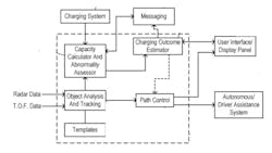
To accomplish this, the vehicle must predict, lock, and track charging coils while modulating draw to avoid either DC-link ripple or driveline torque disturbances. Needless to say, all of these goals and systems interact, adding to the engineering challenges involved.
What’s the Difference Between New Build and Retrofitting for Inductive?
Designing and building an EV to use in-road charging, particularly when underway and at-speed, is far and away the best-case for engineers. This presents opportunity to integrate coils into the floor pan, design hard points for loads, safely route high-voltage wiring, and co-design aero shields and thermal paths with the full vehicle team. Additional benefits include the potential to consider “tune” suspension kinematics and ride height targets for optimal coupling.
Unsurprisingly, retrofits are a much more challenging problem. It can be difficult to find space near the centerline, prime real estate for coil placement. Retrofitting also implies challenges in mounting and perhaps reinforcing areas of the vehicle to handle different or new mechanical loads.
Other challenges include how to freshly route high-voltage (HV) cabling, add reinforcement, route HV cables, certify crash worthiness, apply and meet IP67/69K intrusion prevention guidance, corrosion resistance, and impacts on EMC. The upshot, especially for retrofit designs, is that charging on-the-go will likely have weight penalties.
Since underway charging will be introduced gradually, existing charging ecosystems need to be continued and maintained. Vehicles will likely continue to need DC fast and AC/NACS ports, with inductive simply added as a third path. But BMS and charging ECUs with updatable software will need to be able to arbitrate sources.
Some additional considerations for retrofitting include:
Vehicle dynamics: Added mass should generally be placed low and centrally in a vehicle, which should minimize impacts.
Serviceability: Consider bolt-on charging pad replacement and accessible connectors; provide diagnostics for foreign object detection (FOD).
Some Considerations When Selecting Charging Pads
Light-duty pads are typically ~10–25 kg, including coil, ferrite, shield, housing, harness), and higher-power variants trend heavier. Keeping the stack to <25 to 35 mm below the belly pan will generally preserve needed clearances and have minimal impact on aerodynamics.
The applicable standards generally require foreign-object detection, living-object protection, automatic derate/shutoff, and strict stray-field limits. This can’t be added at the end but must be woven into all decision-making. Therefore, pads must survive stone strikes, water/salt spray, and vibration. Potting and gasket designs will require particular attention. Even road grime can detune coupling, so self-test and adaptive matching will likely be needed to help maintain efficiency.
What are Some of the Applicable Standards?
Standards are emerging or existing in many relevant areas. For example, in the area of wireless power transfer (WPT), the SAE J2954 standard sets out how different vehicles and charging pads should communicate and align. This paves the way for cross-brand compatibility and a more predictable charging experience.
The International Organization for Standardization (ISO) and the International Electrotechnical Commission (IEC) also collaborate on standards for WPT. ISO 5474-4:2025, for instance, defines safety and interoperability requirements specifically for the on-board vehicle equipment.
The IEC 61980 series of standards covers the general requirements for WPT systems in EVs, including electrical safety, efficiency, communication, and electromagnetic compatibility (EMC). Different parts of the standard address specific components or applications.
- IEC 61980-4 for high-power WPT
- IEC 61980-5 for dynamic WPT (charging in motion)
Though focused on conductive charging using a three-phase coupler, the SAE J3068 standard defines digital communication and control protocols that can influence broader EV charging infrastructure, including power-management systems.
Final Thoughts on Inductive Charging
Inductive in-road charging is feasible now, but success rides on packaging, shielding, thermal, and controls co-design. New EV platforms can integrate cleanly while retrofits are possible, but likely with far more compromises. Vehicle pads aren’t prohibitively heavy, but they demand rigorous safety, sealing, and EMC engineering to be truly “fit-and-forget” for process-grade reliability.
References
An Overview of Dynamic Inductive Charging for Electric Vehicles
>>Download the PDF of this article
About the Author

Alan Earls
Contributing Editor
Comment About the Article
To join the conversation, and become an exclusive member of Electronic Design, create an account today!

Leaders relevant to this article: