How to Design Very Wide Loop BW High-Performance PLL Frequency Synthesizers (Part 1)
What you’ll learn:
- A special technique to produce very wide loop BWs in high-frequency PLLs, and, hence, indirect (PLL) synthesizers, thereby achieving very low phase noise rivaling that of direct (MMD) synthesizers.
- A modified standard PLL design procedure for a Type 2 - 2nd Order system with a 1st Order active proportional-integral (PI) loop filter, which uses the special technique.
- A method of modeling and simulating complex PLL topologies using the high degree of flexibility of a general frequency-domain simulator, rather than using the limited degree of flexibility of a specific PLL simulator, which is meant for simple PLL topologies.
This is Part 1 of a three-part series.
As modern wireless communications systems (mainly superheterodyne radio transceivers) are now required to deliver higher performance than ever before, they’re placing greater demands on the frequency sources for these systems. Such systems are moving higher in frequency (millimeter-wave, or mmWave, and possibly terahertz regions), tuning wider bandwidths (BWs), thus processing more complex waveforms using more elaborate modulation schemes and operating in fast tuning modes.
This is happening in both the commercial and military arenas; examples include satellite communications and repeaters, terrestrial wireless systems such as the present 5G15,16 and eventually 6G17,18 protocols, and tactical line-of-sight radios, among others. Therefore, the frequency sources, and particularly the local oscillators (LOs) for these systems, must also move commensurately higher in frequency and deliver higher performance in terms of low phase noise (the primary interest), low spurious, and fast tuning speed.
In some cases, LOs using direct (mix-multiply-divide, MMD) synthesizers are needed to achieve this performance, but they’re usually not the lowest in size, weight, and power (SWaP), cost, and complexity. However, in many cases, LOs using indirect (phase-locked loop, or PLL) synthesizers can be utilized with excellent results, rivaling the performance of direct synthesizers. And they’re usually lowest in SWAP, cost and complexity, which is our thesis here.
For our case of PLL synthesizers and, concerning our priority interest in low phase noise, this means that, for the relevant PLLs, as their operating frequencies become higher, their loop BWs must become commensurately wider (i.e., fractional loop BW is the ultimate interest) to achieve low phase noise. By applying the special technique shown here, it’s possible to achieve very wide loop BWs in such synthesizers, which can’t be achieved by conventional methods.
>>Download the PDF of this article, and check out Parts 2 and 3 of this series


In terms of “relevant PLLs,” we mean those PLLs comprising the synthesizer that have significant influence on the operating band phase noise. For multiple PLL systems, this usually means the output PLL, which is normally the highest-frequency PLL.
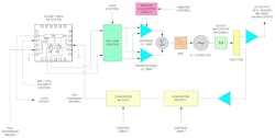
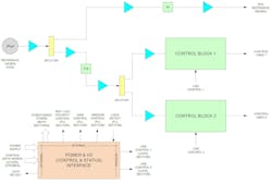
In addition to the use of very wide loop BWs, the use of unity closed-loop (CL) gain along with only internal (within any relevant PLL) multiplication also assists in achieving low phase noise. The technique is applied here to an example synthesizer (see figures below) that’s a single-loop (thereby having only one relevant PLL, simplifying the situation), Type 2 - 2nd Order system with a 1st Order active proportional-integral (PI) loop filter, which is used as a local oscillator in an actual working and fielded high-performance receiver.
The 1st Order active PI loop filter is widely used, so the technique has broad applicability. It can also be applied to PLLs using other topologies with appropriate modifications. The example synthesizer is based on analog hardware because of the high-frequency loop dynamics involved, rather than digital (or computed) hardware/software approaches, which are limited by present-day computing speeds.
Description of the Technique
The technique is fairly simple and can be found in applicable literature.1,2 However, before discussing the methodology, it’s advantageous to preface the discussion with some points concerning analog hardware PLL synthesizers. That said, aside from performance specifications defining the topology, there are normally five major circuit implementation factors to consider for any relevant PLL:
- Discrete vs. IC or combination systems
- Voltage vs. current output phase detection
- Single vs. dual (not differential) output phase detection
- Low-voltage vs. high-voltage output phase detection
- Low-voltage vs. high-voltage voltage-controlled-oscillator (VCO) control
The technique discussed here is applicable when low-voltage output phase detection is combined with high-voltage VCO control, which covers many important applications. This includes our example that requires high performance, since high-voltage VCOs provide high performance in terms of low phase noise (and low reference spurious) due to having relatively low VCO constant Kv,6 compared to low-voltage VCOs.
The technique, as applied to our example synthesizer that is a single-loop, Type 2 - 2nd Order system with a 1st Order Active PI loop filter, involves taking the loop filter using a single active device (normally an op amp) and splitting the proportional and integral functions into two separate parallel paths. Each path would use its own active devices, with the devices having BWs commensurate with their functions. Then the outputs would be recombined or summed to provide a common VCO control signal. It will be referred to as the “dual-path” technique, and we’ll refer to the loop filter as a 1st Order dual-path active PI loop filter.
Such a technique is necessary when a single op amp having very high gain-BW product, very low equivalent voltage and current noise, and high DC supply voltage capability is unavailable to be used as both proportional and integral amplifiers, which was the situation in our case. The approach isn’t new, as it has been known for many years, but it’s not known to have been applied until now and as described here. However, it may start to be more widely implemented due to the reasoning discussed above.
Example Frequency Synthesizer Application and Specs
As was mentioned above, and discussed in more detail here, an example single-loop PLL synthesizer used as a high-side 1st LO in an actual working and fielded high-performance (i.e., high frequency, wideband, complex demodulation, and fast tuning) superheterodyne receiver,5 is presented with the priority interest being in producing the lowest possible phase noise. Producing the lowest possible phase noise for the synthesizer is important, as the 1st LO would be the highest contributor to overall receiver phase noise.
>>Download the PDF of this article
Specifications are as follows:
- Operating band: 22.5 - 39.9 GHz (upper microwave / lower mmWave territory)
- Channel spacing / Number of operating frequencies: 200 MHz / 88
- Reference frequency / Range: 400 MHz (fixed)
- Phase continuity: Continuous for adjacent channel step phase and frequency
- Stability: Phase margin (fm) > 45°, gain margin (Gm) > 10 dB
- Single-side-band (SSB) phase noise: < 350 mdeg, integrated over offset frequencies from 100 Hz to 40 MHz
- Spurious:
- −60 dBc within ±500 MHz of carrier
- −90 dBm within ±(500 to 2,000) MHz offset from carrier
- Switching time: < 25 µs between any two random channels, from unspecified transient overshoot to steady-state frequency offset of < 100 kHz (< 5.75 PPM over full (end-to-end) operating band and < 500 PPM between adjacent channels) and to within output power window of +12 ±4 dBm
- Output power and flatness: +12 ±4 dBm over operating band (without active power leveling)
- DC operating power: 12.5 W maximum
- Environment: Operating temperature range of −20 to +70°C case
Because of the high frequency and high performance of the synthesizer, the components used are all discrete. Also, all parts are of the packaged surface-mount variety (i.e., hybrid chip-and-wire technology isn’t used). These are, of course, the electrical and environmental specifications only; mechanical specifications aren’t included.
The above information is used in Part 2, where the example synthesizer general design approach and detailed design, which incorporates the technique, are discussed.
Acknowledgements
This paper represents the coalescence, organization, and technical writing by the author of the work done by a number of top technical professionals with expertise in frequency synthesizers, radio/radar, and communications systems. It especially represents the work done by Ben Nardi staff scientist and subject-matter expert in these areas who initiated the synthesizer concept and original design, and who produced a prototype unit.
It was a pleasure for the author to have worked with and to have exchanged ideas with these professionals and, particularly, Mr. Nardi. It allowed the author to assume leadership of the synthesizer with his own team, thereby adding his own ideas and developing it to its final production condition. This gave the author the ability to write this paper and, in doing so, further solidified and expanded his knowledge of the subject of PLLs and indirect (PLL) synthesizers.
References
1. F.M. Gardner, Phaselock Techniques, 3rd ed., Wiley, Hoboken, NJ, 2005.
2. R.E. Best, Phase-Locked Loops, Design, Simulation and Applications, 6th ed., McGraw-Hill, New York, 2007.
3. P.V. Brennan, Phase-Locked Loops: Principles and Practice, McGraw-Hill, New York, 1996.
4. E. Drucker, “Phase Lock Loops and Frequency Synthesis for Wireless Engineers,” 1997, Frequency Synthesis & Phase-Locked Loop Design, three-day short course, Besser Associates, Mountain View, CA, 1999.
5. B. Nardi, personal communication, Gaithersburg, MD, 2008.
6. A. Harney, “Designing High-Performance Phase-Locked Loops with High-Voltage VCOs,” Analog Dialogue 43-12, Analog Devices, December 2009.
7. R.C. Dorf and R.H. Bishop, Modern Control Systems, 9th ed., Prentice-Hall, Upper Saddle River, NJ, 2001.
8. W. J. Palm, III, Modeling, Analysis, and Control of Dynamic Systems, 2nd ed., Wiley, New York, 2000.
9. G. Ellis, Control System Design Guide, 2nd ed., Academic Press, San Diego, 2000.
10. W.H. Hayward, Introduction to Radio Frequency Design, Prentice-Hall, Englewood Cliffs, NJ, 1982.
11. S.A. Sedra and K.C. Smith, Microelectronic Circuits, 6th ed., Oxford University Press, New York, 2010.
12. Control System Development Using Dynamic Signal Analyzers, Application Note 243-2, Hewlett-Packard Co., Palo Alto, CA, 1984.
13. Motorola Communications Device Data, Data Book, DL136/D, REV 4, Phoenix, AZ, 1995.
14. F.C. Weist, “Phase Locked Loop Basics for Frequency Synthesizer Applications,” 2010, short course presentation (© 2010 by Frederick Weist), Clarksburg, MD, 2010.
15. “What Frequency Bands Will Roll Out the Carpet for an Official 5G Standard?,” Microwaves & RF magazine, Vol. 56, No. 6, June 2017, p. 20.
16. “Navigating the 5G NR Standards,” Microwave Journal, Vol. 61, No. 12, December 2018, p. 72.
17. S. Pongratz, “6G and The Long RF Journey Ahead," Microwave Journal, ePublishing Online Article, February 2024.
18. C.-X. Wang et al., “On the Road to 6G: Visions, Requirements, Key Technologies and Testbeds,” IEEE Communications Surveys & Tutorials, Vol. 25, No. 2, Second Quarter 2023, pp. 905–974.
>>Download the PDF of this article, and check out Parts 2 and 3 of this series
About the Author

Frederick Weist
Principal, FCW Sciences
Frederick Weist presently resides in Point Of Rocks, Md. He was born in Philadelphia, Pa., on March 25, 1959. He obtained his BS in physics from Drexel University, Philadelphia, in 1983 and his MS in physics from the same institution in 1992.
He is presently (semi-) retired, but continues his interest in STEM research, writing and publishing by working as Owner, FCW Sciences, Point Of Rocks, Md. His last position was as Principal Engineer / SME with Boeing Co. - Digital Receiver Technology Subsidiary, Germantown, Md. Previously he held positions as Consultant with Planar Monolithics Industries (PMI), Senior Design Engineer with Kratos Defense and Security Solutions - Herley-CTI Division, Principal Engineer with DRS Technologies - Signal Solutions Division, Senior Engineer with Aydin Corp. - Telemetry Division and Electronics Engineer with the U.S. Naval Air Warfare Center - Aircraft Division (NAWCAD).
His previous interests included research, design, and development of systems from DC to 42 GHz, specializing in PLLs, frequency synthesizers, transceivers, subsystems, and components. He has also worked in the fields of servos, sonar, photonics, magnetics, and superconductivity. His present interests include the same as well as integrated microwave / photonics (IMWP), quantum, and biophysics systems.
He is a member of the American Physical Society and the Institute of Electrical and Electronics Engineers.
Comment About the Article
To join the conversation, and become an exclusive member of Electronic Design, create an account today!

Leaders relevant to this article: