Clock Domain Crossing and Synchronizers (Part 2): Best Practices
What you'll learn:
- Why modern chips use multiple clock domains — and the metastability risks introduced by them.
- How multi-stage flip-flop synchronizers reduce clock domain crossing (CDC) challenges and improve reliability.
- Key design tradeoffs (reliability, power, area) and best practices for implementing robust synchronizers.
As chip designs grow in complexity and face tighter power constraints, depending on a single clock domain is no longer practical. Instead, most modern chips incorporate as many as dozens or even hundreds of asynchronous clocks.
However, transferring data between two asynchronous domains can cause clock domain crossing (CDC) challenges. One of the most critical issues is metastability, which may disrupt logic and potentially cause system failure. To reduce the risk of metastability, chip designers chain together flip-flops into synchronizers. These components make sure signals are stable before they continue through the rest of the logic.
In most cases today, process design kits (PDKs) include pre-designed synchronizers that can simply be instantiated and used at the CDC interface. Whether you’re choosing a pre-modeled synchronizer or designing one from scratch to meet design specifications, it typically must have high mean time between failure (MTBF) while also striking the right balance between power consumption and area utilization.
Understanding Synchronizers and Best Practices for Using Them
The most widely used type of synchronizer is the two-stage flip-flop chain: The asynchronous signal is captured by a first flip-flop in the destination clock domain, and its output then moves to a second flip-flop. The additional stage gives the first device time to resolve any metastability before it can negatively impact the system.
At very high speeds, engineers can extend the approach to three or even four stages. This provides additional time for any metastability to resolve before the signal is used.
>>Download the PDF of this article, and check out Part 1 of this article series

One of the most important goals during the design of any synchronizer is maximizing the MTBF. Since metastability can’t be entirely eliminated, engineers quantify its risk using the MTBF, which estimates the average time between events where metastability leads to a system-level failure. So, the higher the MTBF, the more robust the overall design.
When it comes to improving the MTBF, the most dominant factor under a designer’s control is the exponential dependency of the flip-flop on the resolution time (Tr) and the number of stages (n), and your aperture time (Ta). All are governed by Equation 1.
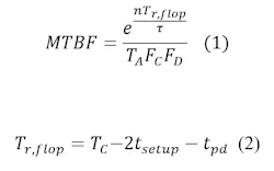
To improve the Ta and the Tr given by Equation 2, we need to speed up the cell, decreasing its setup (tsetup) and hold time (thold). We can achieve that by using low-Vth cells as they have faster switching speed and smaller setup and hold time compared to standard Vth cells. Using low-Vth synchronizer cells might increase the leakage power, but it will greatly affect the MTBF.
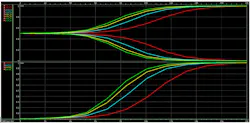
The figure shows the resolution of the metastability induced in four different master latches with different flavors, all having the same starting voltage difference (Vin). The different Vth latches used in this comparison are high Vth, regular Vth, low Vth, and ultra-low Vth. We can see that the ultra-low Vth (SLT) latch-based has the fastest resolution time, while the high Vth (HVT) latch-based has the slowest resolution time. The bottom picture depicts the voltage difference between the nodes represented on a logarithmic scale.
The other dominant factor in the MTBF exponential term is the number of synchronizer stages (n). Increasing the number of flip-flop stages will increase the MTBF exponentially as well, but in turn, it will increase the area, leakage power, and number of cycles after which the data can be sampled safely.
Sometimes the available synchronizers may not meet the required MTBF specifications. In other situations, they may not have enough stages, or the PDK may not have synchronizer cells at all. In that case, it will be necessary to instantiate, connect, and pre-map the flip-flops, to form a multi-stage synchronizer with the required configuration and specs.
Ultimately, it’s key to eliminate any stage delay tpd that might arise due to the placing and connecting of the pre-mapped flip-flops. This will directly affect the Tr given by Equation 2, impacting the overall MTBF exponentially.
When placing a pre-mapped multi-stage synchronizer, engineers must ensure that the flip-flops are placed closely together to decrease any wire delay as much as possible. They also must make sure that no buffers or inverters are placed between them.
Under normal circumstances, the flip-flops are to be placed closely together, directly connected to each other with no logic in between. However, the place-and-route (PnR) tool may encounter hold violations and start inserting buffers between the synchronizer's flops. These hold violations are bogus and can be misleading. The system is already in a metastable state and the flip-flops with their current configuration are trying to resolve it.
That’s not a normal timing path with a stable 1 or 0 trying to get latched to the flip-flop and violates hold. On the contrary, this increases the stage delay tpd and decreases the time the flip-flops have to resolve the metastability Tr.
To avoid that, a false path constraint can be applied between the flip-flops. It will prevent any modification or optimization the tool might perform on these paths. Disable timing constraint shouldn’t be used instead of false path. This signal is crossing to a different domain and has an infinite arrival time window, which can cause crosstalk and induce noise violations. The tool should take this into consideration.
Using Synchronizers to Reduce the Risk of Metastability
There are several best practices for engineers to maximize the MTBF of synchronizers and minimize the risk of metastability:
- Use low-voltage threshold flip-flops synchronizers with small setup and aperture time.
- Use multiple flip-flop stages to improve signal integrity.
- In case of pre-mapping a flip-flop synchronizer, it’s necessary to:
- Place the flip-flop stages as close as possible to each other.
- Prevent the tool from placing any buffers in between the flip-flop stages.
>>Download the PDF of this article, and check out Part 1 of this article series
About the Author
SeifEldeen Emad Abdalazeem
Senior ASIC Physical Design Engineer, Si-Vision
SeifEldeen Emad Abdalazeem holds a Bachelor's degree in Nanotechnology and Nanoelectronics Engineering from Zewail City of Science and Technology, Cairo, Egypt. He specializes in PnR, STA timing analysis, and design closure on advanced technology nodes and high-speed designs.
Comment About the Article
To join the conversation, and become an exclusive member of Electronic Design, create an account today!

Leaders relevant to this article: