Arduino’s New Modulino Boards Tackle I2C and Motor-Control Limits
What you'll learn:
- How the Modulino Hub isolates duplicate I2C addresses across eight switchable channels and can scale to 64 downstream segments.
- How the Modulino Extender uses the LTC4311 bus accelerator to improve I2C signal integrity across cable runs up to 30 meters.
- How Modulino Motors combines an STM32 MCU and MAX22211 dual H-bridge with protection for 5- to 24-V motor loads.
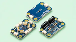
Arduino’s Modulino platform makes it easier for developers to build projects from modular sensor and actuator boards. It simplifies wiring by using I2C and QWIIC connectors. The three latest additions address common challenges: The Modulino Hub expands I2C connectivity for address conflicts, the Modulino Extender supports longer cables, and Modulino Motors handles high-current motor control (Fig. 1).
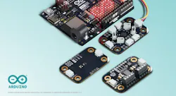
Address conflicts are a major limitation of I2C in complex sensor networks, which can occur when multiple identical sensors share a bus. A unique address must be configured for each device, allowing the MCU to identify it.
I2C supports 7-bit addressing, providing up to 127 device addresses on a bus. Transactions begin with a start condition followed by an 8-bit address frame. The first seven bits represent the target device, while the eighth bit is a read/write flag indicating if the controller receives or transmits data. All devices monitor this frame, responding when the address matches their own.
However, the 127-address theoretical limit rarely translates into 127 usable devices. Most sensors rely on a fixed factory address, which can be modified through one or two jumpers or configuration options. So, deploying multiple identical sensors can overwhelm the available addresses. This produces conflicts that prevent the MCU from communicating with each device.
Modulino Hub
Arduino’s Modulino Hub uses Texas Instruments’ TCA9548ARGER I2C multiplexer to solve the I2C conflicts (Fig. 2). It splits a single connection into eight switchable downstream channels. Channels have pull-up resistors and can be enabled or disabled through the multiplexer’s control register. Each of the register’s eight bits corresponds to one channel. Once it powers up, all channels are disabled.
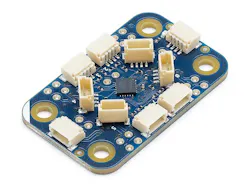
Connected peripherals are off the main bus until they become enabled. Activating a channel enables the MCU to communicate with devices on that segment via the main I2C connection. Sensors with conflicting addresses can coexist if they’re placed on separate channels,
The Hub is addressed as an I2C device on the upstream bus, with 0x70 as its default. Three solder jumpers provide eight selectable addresses from 0x70 to 0x77, which means eight Hubs can operate on the same bus. Since each Hub provides eight downstream channels, one upstream bus could accommodate up to 64 switchable I2C segments.
In addition, I2C isn’t suitable for long cable runs. Its open-drain signaling relies on pull-up resistors to return the bus to a logic-high state. This works over short PCB traces, but sensors connected to longer cables add parasitic capacitance — charged by the pull-up resistor. That boosts signal rise time and makes clock edges slower and more difficult to detect. Bus capacitance is limited to 400 pF, and a 10-meter cable can exceed 1,000 pF, which may lead to communication errors or bus lockups.
Deploying smaller pull-up resistors may speed up the rising edge. However, it also uses up more current, and the open-drain transistor needs to sink current when pulling the line low. If the resistance is too low, the transistor may not be able to establish a logic-low level.
Modulino Extender
To address that I2C cable-length limitation, Arduino unveiled the Modulino Extender (Fig. 3). It uses Analog Devices’ LTC4311 bus accelerator, which supplies more pull-up current while undergoing low-to-high transitions. This boosts signal slew rate and offsets longer cables’ increased capacitance, generating cleaner rising edges compared to pull-up resistors.
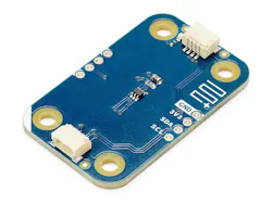
The signal enhancement works without changing the I2C protocol and supports 100-kHz standard-mode and 400-kHz fast-mode operation. In tests, the Modulino Extender communicated reliably over cables up to 30 meters.
Motors are another problem as they consume more power than sensors — a challenging load for embedded controllers. Startup and rapid switching usually generate high current draw and voltage transients. A stalled motor draws too much current, overheating the system.
Reliable motor-control designs need more than a basic driver. They require transient and reverse-polarity protection, current and thermal monitoring, and isolation between the motor and control circuitry. Adding more motors to a system makes those requirements harder to manage due to the hardware and software complexity.
Modulino Motors
Modulino Motors integrates motor-control hardware and protection onto a single board (Fig. 4). It comes with an STM32 MCU and a MAX22211 dual H-bridge for controlling motors through I2C via a QWIIC connector. The design separates the low-voltage logic from the 5- to 24-V motor supply and has TVS diodes for transient suppression and reverse-polarity protection.
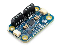
However, the module doesn’t provide active current monitoring or automatic stall detection. Applications will require software safeguards like timeouts to prevent sustained overload.
With these modules, makers can build complex systems without wiring worries. Although prototyping is simpler, they still need to understand the limitations of each board before using them for certain applications.
>>Check out this TechXchange for similarly themed articles and videos

About the Author
 Cabe Atwell
Cabe Atwell
Technology Editor, Electronic Design
Cabe is a Technology Editor for Electronic Design.
Engineer, Machinist, Cartoonist, Maker, Writer. A graduate Electrical Engineer actively plying his expertise in the industry and at his company, Gunhead. When not designing/building, he creates a steady torrent of projects and content in the media world. Many of his projects and articles are online at element14 & SolidSmack, industry-focused work at EETimes & EDN, and offbeat articles at Make Magazine. Currently, you can find him hosting webinars and contributing to Electronic Design and Machine Design.
Cabe is an electrical engineer, design consultant and author with 25 years’ experience. His most recent book is “Essential 555 IC: Design, Configure, and Create Clever Circuits”
Cabe writes the Engineering Life & Engineering on Friday blog on Electronic Design.
See Cabe's cartoons & comic strips here.