Know Your Safety Application Notes (Part 2): Failure Mode Distribution
What you'll learn:
- Specifics on what constitutes a FMEA, FMEDA, and FMECA.
- Breaking down an example FMEDA from IEC 60812:2018.
Check out Part 1 of this series.
Failure modes and effects analysis (FMEA) is a safety analysis tool or method used to evaluate a system or process to define the ways in which it may fail. It also evaluates the effects of such failure modes in the performance of these items and on the surrounding environment. It’s usually iteratively performed to support decisions that reduce the likelihood of failures and their effects, which helps improve the robustness and reliability of systems and processes.1
>>Download the PDF of this article, and check out Parts 1 and 3 of this series


Figure 1 shows what makes up a typical FMEA and some of its well-known variations: FMECA and FMEDA. An FMEA is usually based on information about the system or process, the function to be analyzed, the components making up such a system, the failure modes of each component, its local and global effects, etc.
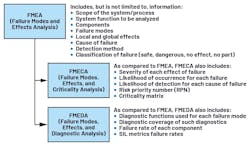
When an FMEA has its failure modes prioritized according to their importance, the process is called failure modes, effects, and criticality analysis (FMECA). When an FMEA employs a measure to show the effectiveness of diagnostic functions, it’s called a failure modes, effects, and diagnostic analysis (FMEDA).1,2
In the design of designing safety-related systems, FMEDA is typically used to provide the following:2
- Device-level failure rate as a function of each failure mode.
- Measure the effectiveness of automatic diagnostic functions.
- Use quantitative reliability analysis in making design decisions.
- Show that resulting designs were better than alternatives.
- Demonstrate that hardware designs comply to IEC 61508 requirements.
An Example FMEDA
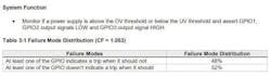
The table shows an example FMEDA from IEC 60812:2018. While the example FMEDA is incomplete,1 it shows how the main parts of a power supply circuit are evaluated. The power-supply circuit uses a linear regulator for internal supply voltages in a device.
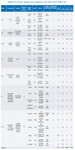
The FMEDA shows different failure-rate values in terms of safe failure rate (λS), no effect failure rate (λNE), dangerous-detected failure rate (λDD), and dangerous-undetected failure rate (λDU) — all of which are important in the calculation of the safe failure fraction (SFF).1
To calculate SFF:3
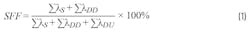
With the existing diagnostic functions only giving a 60% diagnostic coverage for R100 failing short and 0% for IC18’s dangerous failure, the SFF is calculated as 76.94%. If this power-supply circuit is only designed for single-channel systems, it can only achieve SIL 1.3
This design can be further improved to achieve a higher SIL if a diagnostic function is added to cover IC18’s dangerous failure. With a diagnostic function covering IC18’s dangerous failure having 99% diagnostic coverage, its corresponding λDU will become 0.075 FIT from 7.5 FIT, while λDD will become 7.431 FIT from 0.006 FIT, giving a new total λDU of 0.079 FIT, thus an SFF of 99.76%.
To calculate probability of failure per hour (PFH):4

Meanwhile, the power-supply circuit’s total λDU attributes to the probability of dangerous failure requirements of the IEC 615083 standard. Lowering the safety-related system’s total λDU, including the power-supply circuit and its diagnostics, will correspond to a lower average frequency of dangerous PFH, thus equating to better SIL compliance.4
Notably, three columns affect the failure rate outcomes of the FMEDA as shown in the table. Such columns pertain to failure rate per component, FMD, and diagnostic coverage. Component failure rates usually come from component manufacturers; reliability prediction methods are also available to calculate these rates.
FMD, on the other hand, is the proportion of the total component failure rate that can be assigned to each of its failure modes. Such distribution usually comes from the component manufacturer as well.
Lastly, diagnostic coverage refers to the ability of the diagnostic function used to detect failures. This is the only factor that system integrators can optimize in their design by adding diagnostic functions or using better diagnostics.
Speeding Up a System’s FMEDA
Part 1 of this series showed how the LTC2933’s safety application note provides the base failure rates based on different reliability prediction methods. With such an IC’s failure rates and the readily available FMD information in the same document as shown in Figure 2, completing the system FMEDA with the IC’s information will be faster. Such a safety application note also shows the assumed system function as well as the application circuit considered wherein the IC is used.
With ADI’s safety application notes, safety analysis can be more accurate. The information comes straight from a component manufacturer as opposed to just allocating the entire failure rate to lambda dangerous or assuming a certain FMD from a specific assumption.
References
1. “IEC 60812:2018. Failure Modes and Effects Analysis (FMEA and FMECA).” International Electrotechnical Commission, 2018.
2. Paddy Healy. “What Is a FMEDA?” Exida, April 2023.
3. “IEC 61508 All Parts, Functional Safety of Electrical/Electronic/Programmable Electronic Safety-Related Systems.” International Electrotechnical Commission, 2010.
4. Loren Stewart. “Back to Basics 17 - PFH.” Exida, November 2019.
>>Download the PDF of this article, and check out Parts 1 and 3 of this series
About the Author
Bryan Angelo Borres
Senior Power Applications Engineer, Analog Devices Inc.
Bryan Angelo Borres is a TÜV-certified functional-safety engineer who currently works on several industrial functional-safety projects. As a senior power applications engineer, he helps system integrators design functionally safe power architectures that comply to industrial functional-safety standards such as the IEC 61508. Recently, he became a member of the IEC National Committee of the Philippines to IEC TC65/SC65A and IEEE Functional Safety Standards Committee. Bryan has a postgraduate diploma in power electronics and more than seven years of extensive experience in designing efficient and robust power electronics systems.
Comment About the Article
To join the conversation, and become an exclusive member of Electronic Design, create an account today!

Leaders relevant to this article: