Insulate High-Performance Busbars with Modern Powder Coating
What you’ll learn:
- The benefits of powder coating as a leading insulation method: strong dielectric performance, durability, and support for complex shapes.
- Busbar architectures and the reasons why insulation is critical to modern, high-density, high-power designs.
- Details on powder formulations, application methods, masking considerations, and essential testing for reliability.
- Guidance on choosing the right insulation approach based on electrical, mechanical, and environmental requirements.
As power electronics continue to become more compact, efficient, and thermally demanding, busbars have taken on a far more engineering-intensive role. Historically viewed as a simple metal conductor, busbars must now satisfy increasingly stringent electrical, mechanical, and environmental requirements.
Whether used in electric vehicles, aerospace platforms, radar systems, industrial power-distribution systems, or even residential breaker panels, a major component of a busbar’s performance and reliability is the device’s insulation system. Among the available insulation approaches, powder coating has emerged as one of the most widely adopted solutions due to the strength, versatility, and compatibility with complex conductor geometries.
Why Busbars Need More Than Just Metal
A busbar is a rigid, low-impedance electrical pathway, often made of copper or aluminum, that carries a current between subsystems or components. Unlike a wire or cable, busbars support higher currents; enable lower inductance paths; integrate multiple connection points, layers, or structures; and can be formed into 2D or 3D solutions.
As designs increase in power density and complexity, the insulating material around the busbar becomes a critical enabler. Included among these insulation strategies are heat-shrink tubing, molded plastics, and laminated dielectrics, as well as powder coating, which provides many benefits.
Not only does powder coating allow users to control the film thickness for specific voltage standoff requirements, but it’s also a reworkable material that can be stripped and reapplied to address new needs. Furthermore, it offers a durable insulation that resists vibration, abrasion, and handling damage.
Engineers typically select powder coatings for busbars when they need uniform dielectric coverage for complex shapes, multi-layer laminated assemblies, or hybrid mechanical/electrical substructures, in addition to traditional single-conductor busbars.
Common Busbar Architectures and How the Powder Coatings are Beneficial
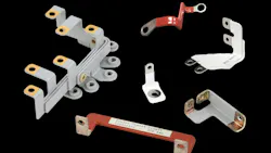
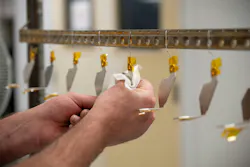
Busbar design varies widely based on the requirements of a system. The specific insulation strategy is tied to the geometry and electrical characteristics of the device, as well as the surrounding environment in which it will be installed (Fig. 1).
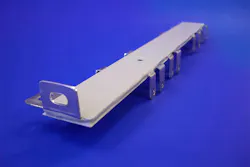
Single-conductor busbars are the simplest of the options. Essentially a shaped metal bar that connects point A to point B, single-conductor busbars are used as wire replacements when low inductance is required, higher current capacities are needed, and/or a rigid mechanical interface is beneficial. Powder coating is ideal for these applications because the consistent film thickness provides predictable dielectric strength along the busbar, whether linear or bent.
Multi-termination busbars incorporate multiple — sometimes dozens or even hundreds — of termination points that branch off a single conductor. These are commonly found in aerospace wiring, vehicle power distribution modules, and radar or sensor systems that require numerous grounding or power taps. Since masking is required for every non-insulated attachment point, these applications benefit from the precision of manual masking and controlled spray deposition that’s standard with powder coating solutions.
>>Download the PDF of this article
Multi-layer laminated busbars describe solutions where multiple conductors are stacked and separated by insulation layers, such as high-density power electronics. This format reduces inductance by minimizing the loop area and supports complex routing. In these cases, powder coating can be used as the primary insulation between the layers or as the external insulation on a completed assembly. (Note: Some multilayer designs use adhesive film or molded dielectrics between layers while still employing powder coating on the exterior for environmental protection.)
Powder Formulations
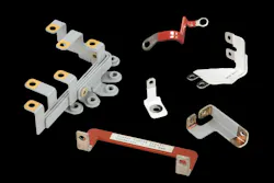
Powder coatings are available in many formulations, including nylon, polyester, polyurethane, hybrid plastics, and others. For electrical busbars, epoxy-based powders tend to be the most preferred as they offer the highest dielectric strength, which makes them ideal for high-voltage standoff, AC-DC insulation, and protection against current leakage (Fig. 2).
Another major engineering advantage of epoxy powders is the ability to strip and reapply the solution. This is critical because tight tolerances might require multiple coat/measure cycles, while damage during installation can be repaired and older assemblies can be refurbished instead of scrapped. For engineers working with specific dielectric targets, film thickness is an important variable that benefits from epoxy-based solutions as additional coats can be added after the initial application.
By contrast, nylon-based powders, while extremely durable, are so chemically resistant that stripping them is nearly impossible. If the nylon powder is applied incorrectly, the part generally becomes unusable.
Compliance and Materials Regulations
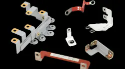
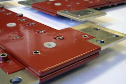
In addition to basic use benefits, powder coating also helps address the environmental and safety standards that are required in many industries. This includes the Europe Union’s REACH (Registration, Evaluation, Authorisation and Restriction of Chemicals) and RoHS (Restriction of Hazardous Substances) directives, which limit harmful materials from being used in electrical and electronic equipment.
Most epoxy powder formulations used in electrical applications will meet those requirements, but it’s important to verify certification for each material before use (Fig. 3).
Methods of Powder Application
When it comes to busbars, two primary powder coating processes are utilized — fluidized bed coating and electrostatic spray coating. Both achieve similar results but are suited to different design needs.
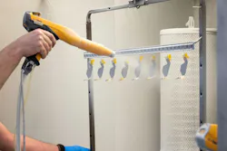
Fluidized bed coating is an older and less commonly used method that remains valuable in situations requiring very thick coatings. Ideal for extremely high-voltage insulation needs, it can generate very thick dielectric layers. However, it may be difficult to control that thickness precisely and is sensitive to timing and temperature variances. Considered outdated for most modern busbar designs, it’s less suitable for intricate geometries (Fig. 4).
Electrostatic spray coating is the industry-standard approach, accounting for approximately 95% of modern busbar powder coating. It offers many advantages, including precise control of film thickness and easy reworkability, which leads to lower waste and fewer scrapped parts. In addition, it’s excellent for complex shapes and multi-termination bars and is compatible with tight dielectric tolerances. Together, these features offer unmatched control for engineers.
Manual Masking and Why It Matters
Masking often dictates the practicality and cost of powder coating a busbar, especially in instances when multiple termination points must remain uncoated. With busbars, there’s usually the need to keep metal exposed on bolted joints, solder terminations, or laminated interfaces. Moreover, complex shapes or solutions with many terminations demand high-precision masking to avoid leakage paths.
Highly automated facilities often struggle with irregular or unique shapes. That’s why manual masking remains the most reliable method for complex or low-volume projects, such as in aerospace, defense, and electric vehicles, where precision is vital (Fig. 5).
Testing and Quality Assurance for Powder-Coated Busbars
Masking can also affect dielectric performance, so ensuring its integrity is essential for applications that require high reliability. Depending on the geometry and electrical requirements of a project, multiple tests can be conducted, such as:
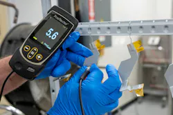
High-potential testing (also known as hi-pot testing) applies to a specific AC-DC conductor voltage while monitoring for leakage through the insulations. To validate that the powder coating achieves the required dielectric withstand, engineers will fully surround the busbar to apply a uniform test across the device at multiple voltage levels to measure leakage current or potential breakdowns.
Sponge testing is a simpler method often reserved for long, linear busbars. It’s particularly effective for detecting microscopic voids that could lead to insulation failure. For these tests, engineers will energize the conductor and then pass a wet, grounded sponge along the powder-coated surface. If the sponge detects a current, it’s a sign that there’s a pinhole, chip, or defect in the coating.
Depending on the application, engineers might also perform continuity and resistance tests for exposed terminals (Fig. 6).
Choosing the Right Insulation Approach
When selecting insulation for a busbar design, engineers should consider the manufacturability, electrical requirements, environmental conditions, and mechanical or geometric constraints. Powder coating is a strong choice when dielectric strength, durability, and geometric versatility are priorities.
Before starting, engineers should consider the manufacturing requirements of the project, such as the masking complexities, lead time, expected production volume, and even the tolerance for reworks.
With electrical requirements, maximum system voltage, required dielectric withstand, AC-DC stress profiles, and clearances and creepage distances will play a critical role in what coating will be ideal. In addition, the number of terminations and bends, thickness tolerance, lamination layers, and mounting surfaces will impact the coating.
When it comes to environmental conditions, manufacturers should rely on the powder suppliers’ technical datasheets for validated performance relative to humidity and salt spray corrosion resistance, altitude/pressure withstand, fungus or microbial resistance, temperature cycling, and thermal shock ratings. There might also be considerations for exposure to oils, fuels, or chemicals.
Bringing It All Together
Powder-coated busbars represent a mature, but continually evolving, technology in electrical system design. As power levels increase and mechanical packaging becomes more constrained, the insulation surrounding a busbar becomes just as critical as the metal inside.
While powder-coated busbars are found across many industries, typical applications include aerospace platforms (aircraft, helicopters, and avionics modules), military vehicles (armored systems and radar installations), electric vehicles, industrial power equipment, residential and commercial breaker panels, and high-density power electronics assemblies. Any system that requires compact, reliable, high-current distribution can benefit from a properly designed and insulated busbar.
By understanding powder formulations, application methods, testing strategies, and design constraints, engineers can specify the busbar insulation system that best meets these demands. No matter the application, powder-coated busbars remain an essential instrument in an electrical designer’s toolkit.
>>Download the PDF of this article
About the Author

Tyler Campagna
Bus Bar Supervisor, Engineering Technician and Assistant Engineering Manager, Custom Electronics Inc.
Tyler Campagna oversees the design, powder coating, and testing of custom busbar solutions at Custom Electronics Inc. (CEI), supporting both customer-specified and fully engineered applications. He works closely with CEI’s quality and compliance teams to ensure products meet stringent military and industrial standards, bringing a hands-on, small-batch manufacturing approach to complex electrical applications.
Comment About the Article
To join the conversation, and become an exclusive member of Electronic Design, create an account today!

Leaders relevant to this article: