Introduction to Control Algorithms in Switching Regulators (.PDF Download)
Feedback-control schemes for linear systems have been around since at least the 17th century, regulating pressure and distance between millstones and then, famously, to control James Watt’s steam engines. These earlier techniques apply to the control of today’s linear voltage regulators.
Currently, switching technology is the preferred option for power conversion. As such, we need to consider controlling output voltage, typically with pulse-width-modulation (PWM) techniques. In this article, we’ll look at three common control methods, along with their pros, cons, and implementations: constant on-time, voltage mode, and current mode.
Constant On-Time Control
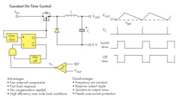
Perhaps the simplest control method used in a buck-converter circuit, constant on-time provides bursts of energy for fixed periods to the output. The repetition rate of the bursts is varied to keep output voltage constant. In Figure 1, a one-shot, or monostable, gives the fixed-length pulse, causing current in the output inductor to rise linearly from its average dc value, charging the output capacitor. After the pulse, the capacitor voltage drops.

1. Constant on-time control is the simplest control scheme used in buck converters.
By initiating the next on-pulse when the voltage drops below a reference value, we can effectively regulate the output voltage, with light loads producing longer off times. The circuit acts like a power oscillator with its positive feedback, so it’s sometimes called a “bang-bang” or “ripple” regulator. Because of the variable off-time, the circuit inherently has a variable frequency.
