A Divide-and-Conquer Approach for Fail-Safe Circuit Protection
What you’ll learn:
- Why traditional circuit protection struggles with modern safety, size, speed, cost, resettability, and increasingly demanding system requirements.
- How decomposition and synthesis distribute safety functions across independent subsystems to achieve higher integrity levels without relying on components.
- How a bidirectional e-fuse architecture shows a scalable, reactive fail-safe approach balancing safety, complexity, cost, and performance.
When it comes to power-path protection, timing is everything. A short circuit can develop in roughly 100 ns. If the fuse or other circuit-protection device can't react within that window, the protected circuitry is exposed to the full fault-energy and is frequently destroyed. That challenge becomes worse in industrial, automotive, and other systems that need to meet strict functional-safety requirements, including SIL 3 and ASIL D.
Traditionally, engineers addressed these requirements by delegating the safety function to a single component designed to fail in a predictable, nonhazardous way. One common example is the pyrotechnic fuse, which blows when overcurrent conditions are detected. Another approach involves the electromechanical contactor. It uses an electromagnetic coil to physically open internal contacts when exposed to excessive currents.
Both methods offer a form of inherently safe circuit protection. However, both devices come with well-known penalties: significant volume and mass, difficult integration, and high recurring costs. More fundamentally, electromechanical devices are simply too slow to interrupt a fault as it happens. They typically have response times measured in milliseconds, which is orders of magnitude longer than the time it takes for a short circuit to occur.
One alternative is the electronic fuse, or e-fuse, which can react in nanoseconds to milliseconds, depending on how its fault-detection and timing functions are configured. But there are challenges with it, too. A safety electronic fuse may be allowed 10 ms to respond to a fault condition at the system level, yet the subsystem responsible for detecting and mitigating the short circuit must react within about 2 µs if the disconnect is to happen without permanent damage.
The traditional fuse closes part of that gap and is unquestionably effective, but it’s a single-use device. Once it blows, the component can't be reset. The system must be physically opened, and the blown fuse replaced.
One potential solution to this is a hardware and software architecture based on the decomposition and synthesis principles of IEC 61508 and ISO 26262. The more distributed approach combines two independent subsystems that are — themselves — less inherently safe. But together, they can achieve a higher overall safety capability. The main advantage is that it works without placing the entire safety function into a fuse, electromechanical relay, or any other all-in-one protection device.
The approach is demonstrated below using a bidirectional e-fuse/arc-fault circuit interrupter (AFCI) as a use case and then generalized into a reusable reactive fail-safe topology.
Fail-Safe Circuit Protection Through Decomposition
Traditional forms of circuit protection are becoming untenable for several reasons. In electric vehicles (EVs), for example, higher DC-bus voltages and currents are coming into play along with the shift to zonal and distributed electrical architectures. At the same time, engineers face tighter constraints on both volume and mass. In other applications, including industrial automation and data centers, designers are also under pressure to enable always-on operation.
As a result, circuit-protection devices increasingly need to support self-test, remote diagnostics, resettable operation, and reliable discrimination between genuine faults and transient conditions such as inrush current.
These demands are driving the shift to compact, software-defined circuit protection. But the move to electronics creates a new challenge: The safety requirements of the system can exceed the capabilities of the components used to implement it. While systems may need to meet standards such as SIL 3 or ASIL D, engineers realistically may only have access to microcontrollers certified at the device level to SIL 2 or ASIL B/C.
Ultimately, many engineers find themselves caught between a mechanical solution that no longer fits the enclosure and a monolithic, electronic solution that can’t be certified at the required level.
One of the main advantages of IEC 61508 and ISO 26262, however, is that they focus primarily on achieving safety at the system level, rather than the component level. The safety integrity level required by a battery-management system (BMS), for instance, can be achieved through the architecture of the overall system without requiring every component in the EV’s battery pack to meet the same level of integrity.
The industrial IEC 61508 standard boils it down into the concept of "synthesis" (IEC 61508-2:2010, §7.4.3), which enables complex safety requirements to be allocated across independent subsystems. When sufficient independence is achieved, the overall safety integrity of the system can exceed that of the individual parts. If the two elements are independent and each supports a systematic capability (SC) of N, their combination may achieve a maximum SC of N+1 (N = 1…3):
- SIL 1 + SIL 1 → SIL 2
- SIL 2 + SIL 2 → SIL 3
Regarding SIL 4, the standard mandates a multichannel implementation (see IEC 61508-2 chapters 7.4.4.3.1 and 7.4.4.3.2). Using multilevel synthesis isn’t allowed — you can't, for instance, combine SIL 2 and SIL 2 to create a SIL 3 subsystem and then add another SIL 3 component to reach SIL 4.
The independence between subsystems can be achieved through several methods:
- Functional diversity
- Technology diversity
- Independent development processes and tools
The ISO 26262 standard used by automotive electronics outlines a similar principle called "decomposition," where the safety goals of the system are split and allocated to independent elements with lower ASIL ratings (Table 1). This is possible as long as engineers can guarantee that these subsystems are sufficiently independent and can operate with freedom from interference.

Safety-Critical Architectures for Circuit Protection
The IEC 61508 standard doesn’t mandate a specific architectural strategy for risk mitigation. However, related standards such as EN 50129 define architectural patterns that can be combined to achieve fail-safe behavior. These patterns are broadly applicable across high-integrity systems. According to EN 50129 Annex B.3, three architectural approaches can be combined to reach a target safety integrity level:
1. Inherent Fail-Safety
Safety is achieved through the physical properties of a single component with non-hazardous failure modes. A typical implementation is an electromechanical relay contact that opens as soon as the coil is de-energized. Galvanic isolation follows the same logic: The withstand voltage of an optocoupler or transformer is set by the dielectric constant and the physical distance of the barrier, which doesn’t drift over operating life.
2. Composite Fail-Safety
The safety function is executed by multiple independent subsystems. Outputs are combined using voting logic, and a permissive decision is only allowed when agreement is reached.
One of the common implementations uses two independent processing paths, each driving its own relay with the contacts wired in series. These channels must both agree to keep power flowing to the load, while either one acting alone is sufficient to remove power. On silicon, the same principle appears as dual-core lockstep with ECC on flash and RAM and independent clock and voltage monitors. Note, though, that a single integrated circuit can’t provide sufficient confidence for SIL 4 on its own, which is precisely why safety integrity must be seen as a system characteristic rather than a component one.
3. Reactive Fail-Safety
A primary subsystem performs the safety function, while a secondary independent subsystem supervises it. When a short circuit or other fault is detected, the secondary subsystem applies a negation function to force the system into a safe state.
Consider a safety-related, position-control motor drive. The main controller closes a fast loop on a coil-based encoder, but motor speed is itself a safety-relevant quantity. A supervisor built on a diverse sensing technology, such as a Hall-based speed sensor, doesn’t replicate that loop. Rather, it verifies it indirectly, integrating the measured response to confirm that the commanded motion from position A to position B actually took place within plausible limits. If the main subsystem fails permanently and speed is no longer correctly controlled, the supervisor shuts down the motor through a solid-state relay (SSR), electromechanical relay, or a traditional fuse.
Because safety integrity is a system-level property, any combination of these approaches may be used to meet the safety goal.
The Differences Between Composite and Reactive Fail-Safety
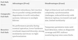
The most common composite architecture is the 2oo2 configuration, as depicted in Figure 1. Two identical subsystems execute the same safety function in parallel. Their outputs are logically ANDed. If a discrepancy occurs, the system transitions to a safe state.
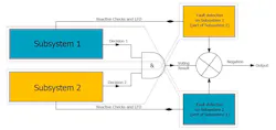
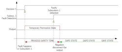
Within the defined process safety time (PST), the healthy subsystem detects the fault in the other branch through cross-checking and can permanently disable the output using negation (Fig. 2).
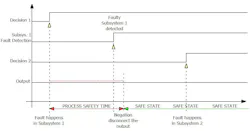
In the reactive architecture (Fig. 3), the main subsystem executes the safety-critical application and operates in real-time. The reactive subsystem continuously monitors the health and behavior of the main subsystem using indirect measurements and diagnostics.
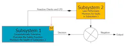
The cost of this arrangement is the latency between when the fault occurs and when the system reacts to it. The benefit is that the supervisor only needs to act within the PST. Because PST is typically longer than the response time of the main subsystem, the reactive subsystem doesn’t require equivalent computational performance. It may detect faults using averaging, plausibility checks, or time‑integrated metrics.
If a permanent fault is detected and not recovered within PST, the reactive subsystem applies negation, forcing the output into a safe state (Fig. 4).
In both composite and reactive approaches, cross-checking between subsystems enables latent failure detection (LFD) and reduces the risk of common-cause failures, provided adequate isolation is implemented (Table 2).
A reactive fail-safe architecture combining a real-time main controller (for instance, dsPIC33A) and an independent monitoring controller (AVR SD) provides an efficient path to high safety level. This pairing offers diversity at the silicon, toolchain, and development-team levels, while maintaining modularity and manageable system complexity.
The next step is to apply these principles in a practical way with the review of a total system solution diagram of a high-current, high-voltage bidirectional e-fuse.
The Reactive Architecture of a Fail-Safe Electronic Fuse
The reactive architecture illustrated in Figure 3 is a bidirectional e-fuse designed for high-voltage, high-current applications requiring elevated safety integrity. Typical deployments are the protection of a DC distribution bus in automotive zonal architectures, DC microgrids, energy storage, and industrial DC backbones, together with the rack and row distribution used in data center and AI-compute infrastructure, where rising power density is pushing busbar voltages toward 800 V DC.
The approach applies equally to any node in which current flows in both directions: a bidirectional on-board charger or V2G/V2L port, a DC fast-charging branch, a battery backup or ride-through unit feeding energy back onto the bus, or a module-level and pack-level disconnect within a reconfigurable battery architecture. In each case, the e-fuse is inserted in series between the power port and the protected load or source, taking over the role traditionally assigned to a melting fuse, a pyrotechnic fuse, or a mechanical contactor.
Within the host system, the e-fuse behaves as an intelligent node rather than a passive protective component. Because the tripping profile is fully software-defined, the same hardware serves loads with very different current signatures and remains immune to false positives such as inrush. As a result, it can be placed upstream of capacitive DC-link, pre-charge circuits, or hot-swappable stages without nuisance tripping.
The current data acquired for protection is reused for higher-level functions, including supervision of the safe-operating area (SOA), arc fault detection, signal-quality estimation, and load-profile recognition through DSP techniques such as fast Fourier transform (FFT), wavelet analysis, in-band power estimation, and correlation. Latent failure detection, e.g., silicon-carbide (SiC) FET leakage measured at two thermal points, whose ratio indicates possible future solid-state switch failure, turns the protection element into a prognostic source, which matters wherever unplanned downtime is expensive.
While the fast, resettable, and software-defined solution handles the primary safety function, the architecture also uses a mechanical disconnect as a sort of last-resort protection mechanism. When the main subsystem mitigates the fault successfully, the load is reconnected as a recovery mechanism, while a permanent main-subsystem failure results in an unrecoverable disconnect within the PST.
The absence of a current zero crossing on a DC bus is the other reason for the electromechanical approach. The SiC module provides the fast solid-state interruption needed to clear the fault, while the air-gap element provides verified galvanic isolation.
All of the major hardware blocks are identified in Figure 5 using numerical references. The application-specific elements are highlighted in pink, while generic or reusable functional blocks are shown in green.
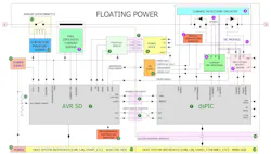
To minimize the risk of common-cause failures, galvanic isolation is implemented between the two subsystems through certified safety components. The isolation boundary (red island) separates the main subsystem, which executes the primary safety functions such as short-circuit handling, overcurrent protection, and overtemperature management, from the reactive subsystem. The reactive subsystem continuously supervises the main subsystem operating conditions and enforces load disconnection in the event of a detected permanent failure.
The Building Blocks of a Functionally Safe E-Fuse
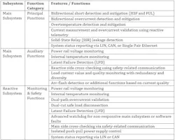
The general system components (green) include (Table 3):
- Microchip dsPIC33A DSC: Main processing unit executing the application safety functions and providing diagnostic feedback to the reactive subsystem.
- AVR SD: Core controller of the reactive subsystem, responsible for continuous supervision of the dsPIC33A operating behavior and validation of correct safety function execution.
- Push-pull driver: Controlled by the reactive subsystem to drive the isolated DC-DC power converter through pulse-width-modulation (PWM) signaling.
- Power block: Regulates, distributes, and monitors the isolated power rails supplying the main subsystem.
- DC-DC converter isolation transformer: Transfers power across the galvanic barrier to the floating main-side circuitry.
- First dual-port isolator: Provides electrical isolation for the advanced watchdog interface and for bidirectional telemetry exchange between subsystems.
- Second dual-port isolator
- OR logic block: Aggregates fault indications from the main subsystem into a single safety-qualified digital fault signal routed to the reactive controller.
- Environmental temperature monitor: Measures ambient temperature conditions on the reactive side.
- Power input monitoring: Supervises the primary supply rail for abnormal undervoltage or overvoltage conditions.
- Power supply: Generates regulated voltages for all reactive subsystem components.
- Airgap disconnect device: Provides intrinsic fail-safe power disconnection capability.
- Disconnect driver: The associated driver for the disconnect controls activation and continuously verifies device health.
- Power port: Primary energy input interface for the system.
- Host system interfaces: Enable communication of status and telemetry between the system, external controllers, and vehicle or equipment networks.
- Additional host system interfaces: Support LIN, CAN, 100BASE-T1S single-pair Ethernet, or standard Ethernet.
- Hall-effect isolated current sensor: Secondary current-sensing element providing galvanically isolated measurements.
- Module temperature monitor: Monitors SiC module temperature, supporting higher-level overcurrent mitigation steps.
- Shunt resistor: Low-temperature-coefficient bidirectional current-sensing element.
- Leakage detection circuit: Detects abnormal leakage currents across SiC FETs during switching transitions.
- SiC module: Bidirectional solid-state switching assembly integrating power FETs, temperature sensing, current shunt, and leakage detection.
- Current preprocessor: Analog front end performing signal conditioning for current measurement.
- Multistage FET driver: Implements staged gate drive control to support safe current validation, pass-through detection, and controlled disconnection during fault events.
Conclusions
The decomposition and synthesis principles presented above are an effective way to achieve high functional safety levels while avoiding the complexity of monolithic safety systems. By partitioning the hardware and software, the new architecture is more scalable for evolving safety requirements and enables optimization of compliant implementation costs without compromising safety objectives.
These benefits are achieved through the selection of two functionally safe Microchip device families: the dsPIC33A DSC as the real-time application safety controller, and the AVR SD as the independent reactive monitoring controller. Both platforms leverage distinct silicon technologies, development flows, and software ecosystems, ensuring architectural diversity.
Check out the application note (DS00006322) for this e-fuse. It features in-depth details on latent and random failure mitigation mechanisms along with guidelines for generalizing the architecture to other end applications.
>>Download the PDF of this article
 dreamstime_christopherewing_1592074
About the Author
 Sacha Prijovic
Sacha Prijovic
Senior Marketing Manager, dsPIC business unit, Microchip Technology
Sacha Prijovic is a veteran of the semiconductor industry with a track record of over 25 years of driving growth and innovation. Holding a degree in electrical engineering, Sacha’s diverse career spans frontline sales, international business development, and his current role in product marketing for Microchip’s Digital Signal Controller division.
Driven by a deep curiosity for systems and market strategies, he seamlessly bridges the gap between engineering concepts and commercially successful applications, helping engineers navigate evolving technological landscapes. His guiding principle: “Everything is relative.”
 Andrei Bucsa
Andrei Bucsa
Senior Technical Staff Engineer–Architect, Microchip Technology
Andrei Bucsa is a Senior Technical Staff Engineer–Architect within Microchip Technology’s dsPIC Architecture group, where he drives the definition and development of next‑generation safety‑enhanced IP. He brings over 29 years of experience in hardware architecture, system design, and product innovation, supported by more than 18 issued patents.
Before joining Microchip, Bucsa worked at Thales as a Hardware Architect for New Products and Innovation, contributing to next generation of SIL4‑grade autonomous train platforms. Beside hardware development his current interests, include agentic AI process optimization and AI-based engineering tool development. Bucsa earned a Diploma Engineer in electrical engineering and holds a master’s degree in EMC from the Technical University of Cluj‑Napoca.
Comment About the Article
To join the conversation, and become an exclusive member of Electronic Design, create an account today!
 Leaders Logo
Leaders relevant to this article: