Protected Power Stages Clamp Peak AI Currents
Modern GPUs can consume huge amounts of power to keep up with AI’s voracity for compute cycles. But the way that these processors draw power is often anything but steady.
Due to the highly dynamic nature of AI training and inference, they experience sudden and large jumps in power demand, surging up and down during each step of the computation. These load transients can cause current requirements to swing dramatically, reaching as much as 2,000 A per microsecond.
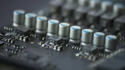
A host of companies are developing multiphase voltage regulators that can handle the fast-changing and high-peak-current demands of AI accelerators and GPUs. One of the most important building blocks is the smart power stage, also known as DrMOS, which integrates the power transistors and gate drivers into a single chip to enable more efficient power conversion. These devices are widely used on accelerator cards and server boards to deliver fast, stable power to processors operating under highly variable AI workloads.
But delivering enough current — and doing it fast enough — is only part of the challenge facing power designers. The other part is protecting the power devices themselves from being overwhelmed by all of that current.
One approach, adopted by Alpha and Omega Semiconductor (AOS) in its SmartClamp series, is to integrate circuit protection into the DrMOS power stages. The SmartClamp devices come with advanced overcurrent protection (OCP) and negative current protection (NCP), ensuring safe, reliable operation for bursty AI workloads.
The buck converters are designed to deal with what the company calls the “the specific ‘stress tests’ of modern AI workloads,” said Zach Zhang, director of product marketing for power ICs.
Featuring peak-to-peak current limiting, AOS said SmartClamp acts as a safeguard for multiphase voltage regulators, helping prevent catastrophic failures in data centers and other areas where high peak currents are the norm.
The Peaks and Valleys of Powering AI Accelerators
The peak current densities encountered with GPUs and other AI accelerators have become extremely hard for power electronics to handle. Even though these processors typically operate at supply voltages under 1 V, the amount of current racing into them is rising to several thousand amps.
Consequently, it’s driving continuous power, also called the thermal design power (TDP), as high as 1,400 W in NVIDIA’s Blackwell GPUs. These power requirements are on the rise, with even higher power levels anticipated for NVIDIA’s Rubin GPUs.
On top of that, these processors can require huge amounts of currents when leaping from idle to full power. That results in rapid load changes and extreme current transients, which can be highly disruptive and even potentially damaging for GPUs or other XPUs. The highly dynamic power demands of AI can produce very large di/dt events lasting several microseconds when ramping up to full load during training, as well as peak currents that may persist for several milliseconds before ramping back down.
In AI systems, peak workloads can push current levels above and beyond the safe limits of conventional power stages as well as the inductors used with them. One of the main risks is inductor saturation, which occurs when very high current drives the magnetic core into saturation, reducing its ability to store energy efficiently. As inductance drops sharply, current can rise rapidly, potentially leading to overheating and efficiency loss while increasing the risk of damage to the MOSFETs.
Traditional approaches to OCP could lead to response delays. Even a 50-ns delay can result in a 30-A overshoot, risking permanent damage to the high-side MOSFET, particularly when inductor saturation occurs. Many DrMOS devices already come with safety mechanisms such as input (VIN) overvoltage protection (OVP), undervoltage-lockout (UVLO) protection, and overtemperature protection (OTP).
The SmartClamp family mitigates this risk by implementing current limiting directly within the power stage rather than relying only on the controller, improving response to load transients that can transpire in tens of nanoseconds.
The Importance of Cycle-By-Cycle Current Limiting
The smart power stage is comprised of low- and high-side MOSFETs with an integrated driver to reduce parasitics. It also leverages an internal ramp-based sensing method that continuously monitors inductor current in real-time, enabling cycle-by-cycle current clamping instead of reacting after fault conditions develop. The cycle-by-cycle control ushers in precise protection against positive and negative current events, even those with high di/dt slew rates.
AOS said SmartClamp also has universal compatibility with industry-standard multiphase controllers, including constant-on-time (COT) and fixed-frequency pulse-width-modulation (PWM) controllers. This flexibility allows for integration into a wide range of system designs, including AI servers. In addition, it works with AOS’s Advanced Transient Modulator (A2TM) multiphase control solutions to provide improved transient response.
With A2TM technology, the system’s bandwidth can be extended. This gives the voltage regulator a better chance at responding to the type of instant and highly dynamic current demand experienced with AI chips.
The SmartClamp power devices, including the AOZ53228QI, AOZ53262QI, and AOZ53263QI, are in full production with 12-week lead times. The AOZ53228QI is priced at $1.40 each in 1,000-unit quantities.
About the Author

James Morra
Senior Editor
James Morra is the senior editor for Electronic Design, covering the semiconductor industry and new technology trends, with a focus on power electronics and power management. He also reports on the business behind electrical engineering, including the electronics supply chain. He joined Electronic Design in 2015 and is based in Chicago, Illinois.