From Concept to Prototype: The Tools of Power-Supply Design
What you'll learn:
- How development tools help guide engineers through the entire power design process, from plotting a system’s power-management architecture all the way to hardware prototyping.
- How simulation environments such as SPICE can be used to fine-tune power-supply designs, lending insight into efficiency, stability, transient response, and more.
- How tools for power-system design, component selection, and digital configuration can help set up engineers for effective hardware evaluation.
Almost all electronic circuits require a power supply, making power-supply design a fundamental skill for most design engineers. As switch-mode power supplies (SMPS) grow in complexity, an entire tool chain has evolved over time to simplify the design process. These tools generally fall into five categories: power system designers, power-supply calculation tools, digital power-supply setting tools, circuit simulation tools, and hardware evaluation tools.
Together, these tools help guide engineers through the entire design process, from plotting a system’s power-management architecture all the way to evaluating performance in hardware. Each tool serves a specific purpose, providing valuable insights at different stages. By leveraging these capabilities, engineers can build better power supplies and validate them faster. The following sections examine each tool and its role in the power-supply design workflow.
What are Power-System Design Tools?
Most electronic systems require more than one power supply. Oftentimes, four or more different power supplies are needed. These power-supply design tools, such as LTpowerPlanner from Analog Devices, are used to lay out the system architecture covering all of these power supplies.
For instance, LTpowerPlanner allows designers to draw a simple block diagram of the different power conversion steps in a circuit. These can be modified in an easy-to-use graphical user interface (GUI). Each power-supply block can be set to an expected power-conversion efficiency so that a user will find the total power-supply architecture efficiency within a few clicks. Figure 1 shows a screenshot of one of those block diagrams with a calculated total efficiency of 86.3%.

The tool helps make basic decisions for the power architecture by selecting DC-DC converters with an individual efficiency to yield an acceptable total power-conversion efficiency. Also, system-level decisions, such as sequencing requirements and capabilities, can be made and recorded.
A Calculated Plan: Power-Supply Calculation Tools
After developing a suitable power-system design, the next step is often the design and optimization of individual DC-DC converters. At this stage, the focus shifts to tailoring each converter to the requirements of the target circuit. One tool commonly used for this task is LTpowerCAD. The software is available as a free download and is installed locally on the user's computer. Network connectivity is required only for software updates and for accurate inductor core-loss calculations.
After launching the tool, a suitable power-converter IC can be selected through a parametric search interface. The designer enters key requirements such as the input voltage range, output voltage, output current, and any additional features, including a power-good signal, frequency synchronization capabilities, or digital interface support. The tool then generates a list of matching devices.
>>Download the PDF of this article, and check out the TechXchange for similar articles and videos


Once a device is selected, a design window opens with recommended values for the required external components. Real-world inductors and capacitors from multiple vendors can be chosen directly from extensive component libraries. These selections are incorporated into a complete circuit analysis that evaluates efficiency, stability, and any additional filtering requirements on the input or output side of the power converter.
When working with the tool, warning messages are given if a component value is chosen with a much lower or higher value than the circuit calculation suggests.
Figure 2 shows the main window for design optimization within LTpowerCAD. The yellow fields display the values calculated by the tool, while the blue fields enable users to enter different values. Designing the circuit of a SMPS becomes simple using this tool.
One of the unique features within LTpowerCAD is the electromagnetic-interference (EMI) filter designer tool (Fig. 3). It can be accessed on the main circuit screen of LTpowerCAD and opens a special filter designer window. The filter designer is useful for figuring out if a power supply requires a special input filter to fulfill conducted EMI specifications such as CISPR 22/CISPR 32, CISPR 25, or MIL-STD-461G emissions. The filter designer plots the emissions of the power converter itself and suggests a suitable input side filter to attenuate conducted EMI.

Besides these main tasks, the filter transfer function (filter attenuation) and the filter impedance are plotted. Filter impedance is very important to ensure that the combination of DC-DC converter and filter is stable.
The Setup: Digital Power-Supply Configuration Tools
Some power supplies are digital. Ones and zeroes can never power a load. What we mean by a digital power supply is a digital circuit within a power-supply regulator IC to control circuit parameters, pull together information about the power supply’s activities (telemetry), and run the complete control loop in the digital domain.
Digital control requires more effort on the engineer’s part to convert the analog signals from the power supply quickly and accurately into digital signals. But as a tradeoff, it offers the ability to digitally adapt the power supply’s control loop.
When evaluating digital power supplies, software tools are needed to interface with the power supply and make various settings to state-machine-based devices. To do that, engineers can download tools such as LTpowerPlay. This graphical user interface, developed by Analog Devices, fully controls digital power supplies. Typically, the software talks to the hardware using a USB to I2C (PMBus) interface. Figure 4 shows the main window of LTpowerPlay, where different settings can be selected and information from the power supply is polled and displayed.

The LTpowerPlay digital power-supply tool can be run as a standalone system in simulation mode, even when no hardware is attached. This makes it possible to quickly learn about a digital power-supply IC without having to spend time reading a long datasheet.
Closing the Circuit with SPICE and Circuit Simulation Tools
Lots of circuit simulation tools are available on the market today. One of the most popular is Analog Devices’ LTspice, which is a full SPICE simulation tool with an intuitive schematic entry tool, a symbol generator, and a waveform viewer. LTSpice was specifically designed for SMPS simulations, and it’s optimized to run these simulations fast. New features are constantly being added, and the speed is increasing over time.
A circuit simulation tool can be a critical add-on to a circuit calculator such as LTpowerCAD. In a simulation tool, a user has increased flexibility to modify a circuit, add circuit parts such as filters, and combine multiple power supplies into one large system to check how multiple power supplies influence each other.
LTSpice and can even help solve specific challenges in power-supply design, such as estimating the effective ripple current in aluminum electrolytic capacitors, which is one of the main limiters of the capacitor’s lifetime and the system’s overall reliability and longevity.
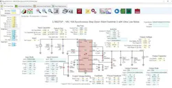
LTspice version 17.1 introduced the frequency response analysis (FRA), which gives engineers a fast and easy way to generate a Bode plot of a power-supply regulation loop and then evaluate it. LTspice version 24 introduced a special FRA probe to enable the plotting of partial transfer functions of a regulation loop, while LTspice version 24.1.8 added the ability to plot Nyquist plots and standard Bode plots. Figure 5 shows a power-management circuit schematic of an isolated DC-DC converter in LTspice.

Besides LTspice, Analog Devices also supports SIMPLIS with a wide range of device models. SIMPLIS is a simulation of piecewise linear systems and is very fast when simulating SMPS.
Circuit calculations and simulations are important steps in the power-supply design process. However, even with modern power-management development tools, validating a design in hardware is still necessary.
While SPICE simulations and other tools can significantly reduce development and evaluation time, they will never be able to replace testing a physical prototype. To speed up hardware validation, a new class of power-supply evaluation environments such as LTpowerAnalyzer has been developed.
LTpowerAnalyzer consists of dedicated hardware that connects to a PC through the ADALM2000 kit. The ADALM2000 acts as a compact oscilloscope and signal generator while also controlling the LTpowerAnalyzer. Figure 6 shows the setup of the LTpowerAnalyzer attached to a design under test (DUT) SMPS board.

This tool can plot the Bode plot of a power supply. It performs life load transient tests for load transients up to 100 A. It’s also able to plot the output impedance of the power supply, which is helpful in discovering if a power supply is compatible with complex (inductive or capacitive) loads. It comes with a software component that will even interface with LTpowerCAD to compare Bode plot calculated results with real hardware measurements. To make things more intuitive, the two plots can be shown in the same window.
Figure 7 shows a screenshot of a Bode plot measurement using the LTpowerAnalyzer’s software.

The Tools of Power-Supply Design Span Concept to Prototype
Designing a power supply can be a much simpler process when using the latest development tools. It’s possible for many optimization tasks to be completed automatically, and information is presented in a clear and accessible manner throughout the workflow. As a result, important design decisions can be made not only by experienced power-management experts, but also by circuit designers whose primary focus lies elsewhere in the system.
Another advantage is that many of these tools are available free of charge. This lowers the barrier to entry and allows designers to start evaluating and using advanced power-supply design tools without requiring an upfront investment.
>>Download the PDF of this article, and check out the TechXchange for similar articles and videos
About the Author

Frederik Dostal
Power-Management Technical Expert
Frederik Dostal is a power-management expert with more than 20 years of experience in this industry. After his studies of microelectronics at the University of Erlangen, Germany, he joined National Semiconductor in 2001, where he worked as a field applications engineer, gaining a lot of experience in implementing power-management solutions in customer projects. During his time at National, he also spent four years in Phoenix, Arizona (USA), working on switch-mode power supplies as an applications engineer.
In 2009, he joined Analog Devices, where since then he held a variety of positions working for the product line and European technical support, and currently brings in his broad design and application knowledge as a power-management expert. Frederik works in the ADI office in Munich, Germany.
Also check out my: