7 EMC Problems Engineers Can Identify Before Formal Compliance Testing
What you’ll learn:
- How to separate an EMC source, coupling path, and radiator instead of changing several design elements at once.
- Which seven recurring hardware problems can often be exposed with controlled pre-compliance measurements.
- How to make relative A/B tests useful without confusing them with formal compliance results.
A formal compliance test is designed to answer a specific question: Can a product meet the requirements of a standard or certification when tested in a defined way? But while the test can determine whether a product passes or fails, it’s not always optimized to explain why a failure occurred.
That distinction matters when it comes to electromagnetic compatibility (EMC) because many of the underlying issues start out as ordinary hardware interactions in, on, or around the PCB. These include return currents taking an unintended path, a cable carrying common-mode current, a power converter exciting an enclosure resonance, or a wireless subsystem changing the current distribution of the finished product.
Pre-compliance work is most useful when it’s treated as part of the broader engineering process rather than as a faster and less-costly version of certification testing. The goal is to reproduce the suspicious behavior, connect it to specific operating conditions, and then identify the source of noise or path of electromagnetic interference (EMI) that most likely caused it. Teams can then evaluate different ways to address the problem.
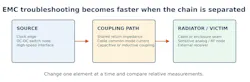
The source-path-radiator model in Figure 1 provides a practical blueprint for that investigation. Ultimately, a source of interference alone doesn’t always create a system-level problem. Energy also needs a path to travel and something that radiates or responds to it as a victim. Below, we explore several EMC problems that engineers can identify and address before getting started with formal compliance testing.
Problem #1: A failure occurs only when two subsystems operate together
A return-path problem often reveals itself indirectly rather than through a visible layout defect or wiring issue. A product may look quiet when its processor, display, motor drive, or radio operates by itself. However, it can generate noise or start malfunctioning when two subsystems are active at the same time. Such behavior suggests shared impedance, reference movement, or a return current being forced through a path used by another circuit.
Start with an operating-state matrix. Measure subsystem A alone, subsystem B alone, and both together while preserving cable placement and test geometry. If the subsystems together produce a signal that they don’t create by themselves, use current probing, local magnetic-field scanning, or controlled temporary return connections to determine where the interaction occurs. This approach converts a broad grounding question into a specific, repeatable symptom.
Problem #2: The spectrum changes when an external connection changes
A strong cable-related clue is sensitivity to the product boundary. A peak can occur when Ethernet, USB, sensor, display, or DC wiring is connected. The noise can change when the cable routing changes, or it may fall when the same function is performed through a shorter lead or one with a different termination. By measuring the response in different situations, engineers can determine whether a cable or its connection to the product is contributing to the EMC problem
Freeze the software mode and power condition, then compare a small set of representative connection states. Measure common-mode current where practical and scan the connector region before changing filters or shielding. Temporary ferrite suppression, connector-reference bonding, or an interface filter can test whether the external conductor is the dominant path.
Stancer Testing-Lab's published conducted-emissions guidance raises a related point: Noise carried on a cable can become radiated energy, and evaluating conducted and radiated emissions separately could obscure the coupling mechanism.
Problem #3: A family of peaks tracks converter frequency or load
Power-converter noise has a useful diagnostic signature: Related peaks often move or change amplitude with switching mode, input voltage, load, or burst operation, all of which can be adjusted to optimize system performance. Instead of starting with a general redesign of the power stage, first ask whether the noise can be traced to one of these variables.
Record the converter state and emissions result together. Compare fixed-frequency and burst modes where the design permits, vary load within normal operating limits, and probe the switch node, inductor, supply connections, and attached cables. If the spectral family follows converter state, test one hypothesis at a time, such as input-filter placement, high-current-loop geometry, exposed switch-node area, or coupling into an external lead.
Similarly, Stancer's conducted-emissions material identifies dominant frequencies, operating modes, filter weaknesses, and DC-DC converter behavior as practical targets for early pre-compliance investigation.
Problem #4: Temporary seam bonding changes only a narrow frequency region
Enclosure leakage can be relatively easy to detect compared to a board-source problem. Even a small mechanical change to the system could produce a frequency-selective response. A removable panel, connector cutout, display opening, gasket transition, or ventilation pattern may matter only after the final enclosure and cable set are installed.
Start by scanning along the finished product’s boundary and recording the locations where the field is strongest. Then use removable conductive tape, temporary bonding, or a controlled cover-state comparison at one location at a time. Take note of situations in which closing one discontinuity repeatedly reduces a narrow group of peaks while the internal source remains unchanged, since it may signal a structural path.
The production solution may involve bonding spacing, gasket compression, aperture treatment, or relocating the source. The pre-compliance testing itself is intended to separate enclosure behavior from source generation.
Problem #5: A victim changes in step with a source even though no direct connection exists
PCB coupling is best treated as a correlation problem. A sensor offset, receiver desensitization, communication error, or spectral component that follows a clock, memory transfer, display refresh, or converter state can reveal a relationship not reflected in the schematic. The goal is to establish that the victim follows the source before deciding whether the dominant path is electric-field, magnetic-field, conducted, or radiated coupling.
Use synchronized operating-state changes and localized measurements. Disable or frequency-shift the suspected source when possible, map the field around both the source and victim, and introduce one reversible barrier or spacing change.
A response that follows the source frequency or duty cycle is stronger evidence of a problem than physical proximity alone. This source-victim correlation approach also prevents unrelated layout changes from being credited for improvements that seem to come out of nowhere.
Problem #6: Radio performance changes only after host integration
A wireless module can behave correctly on its evaluation platform and still show a problem after installation in the complete product. The finished enclosure, processor, display, power system, cables, antenna location, and presence of other radios in the system can change both the intended RF environment and unintended coupling paths.
Compare representative assembly states: development platform versus final PCB, enclosure open versus closed, battery versus external power, cable connected versus disconnected, and each radio alone versus simultaneous operation.
Monitor unwanted emissions together with intended-radio behavior. Stancer Testing-Lab's RF testing page describes this host-level approach directly. Antenna configuration, transmitter operating conditions, integration considerations, and host-device compliance are evaluated together to determine what additional testing may be required. That’s a broader question than whether the module has its own approval.
Problem #7: The result changes even though the product doesn’t change
A pre-compliance change isn’t evidence of a product improvement if the measurement environment changed at the same time. Ambient transmitters, cable routing, grounding, antenna polarization, support-equipment placement, power-source impedance, probe distance, and orientation can all move a result.
Document the complete baseline: operating mode, software version, load, cables, support equipment, orientation, distances, detector and bandwidth settings, and ambient spectrum. Repeat the baseline before and after each modification. Formal facilities control reflections, ambient noise, and measurement geometry to support repeatability. In an ordinary engineering space, ambient scans and disciplined fixtures are essential.
Near-field probes remain valuable for localization, but their response strongly depends on distance and orientation. Therefore, they should be used as controlled relative instruments.
Creating a Pre-Compliance Debugging Loop
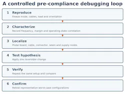
These seven problems are all different, but each one should be investigated in a general way. First, reproduce the issue in a stable configuration. Characterize its frequencies, margin, and correlation with product state. Localize likely sources and paths. Apply one reversible change that tests a hypothesis. Repeat the original measurement, then confirm the result across the representative configurations that matter. Figure 2 summarizes this loop.
Most importantly, don’t confuse the results of pre-compliance testing with formal compliance data. A near-field scan or informal radiated pre-scan usually makes the most sense as a comparative tool when it comes to EMC.
These approaches can show that a peak follows a clock, a cable is carrying common-mode energy, or a targeted change reduces a signature. They don’t establish regulatory compliance by themselves. Tektronix’s practical EMC troubleshooting guidance makes the same distinction: Compliance procedures produce calibrated absolute results, whereas near-field work is largely suited to relative measurements.
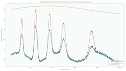
The illustrative comparison in Figure 3 shows the right interpretation. A repeated A/B setup is able to demonstrate that a hypothesis moves several related peaks in the intended direction. It can’t guarantee that the final product will pass every required configuration, detector, frequency range, immunity test, or formal facility setup.
What to Carry into Formal Compliance Testing
Good pre-compliance work produces more than a favorable trace. It produces a controlled configuration, a record of worst-case operating modes, known cable and accessory states, documented design changes, and an explanation of which source-path-radiator mechanisms were tested. That information helps the formal program start with fewer unknowns.
The practical goal isn’t to promise a first-pass result. It’s to find ordinary hardware interactions while the team can still change them, replace broad redesign with focused hypotheses, and enter formal testing with a more stable product and a clearer test plan.
>>Download the PDF of this article
 dreamstime_aialekseigorodenkov_308301127
About the Author
Reza Khalvandi
Engineer, Stancer Testing-Lab
Reza Khalvandi is an engineer with Stancer Testing-Lab in Laval, Quebec. His work connects hardware-development teams with EMC/RF pre-compliance, formal testing, and engineering troubleshooting. His technical interests include scalable wireless networks, RF systems, and practical methods for reducing uncertainty between prototype development and compliance testing.
Comment About the Article
To join the conversation, and become an exclusive member of Electronic Design, create an account today!
 Leaders Logo
Leaders relevant to this article: