Microcontroller Efficiently Converts Sensor Voltage to Current (.PDF Download)
When taking measurements from analog sensors located at long distances, voltage drops and noise can affect precision of the readings. Therefore, a voltage-to-current (V/I) module is needed to transmit a current in order to obtain accurate readings. The reason is well-known: According to Kirchhoff’s current law (KCL), the sum of currents entering a node must be equal to the current leaving that node; thus, the sensor’s cable length is irrelevant when transmitting current and further, the low impedance of a current loop minimizes noise pickup in contrast to a voltage signal.
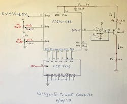
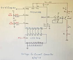
1. This circuit, based on a PIC microcontroller with a few added components, converts a sensor-based voltage into a 4- to 20-mA current loop. Shown is the circuit as originally drawn on a whiteboard.
The circuit in Figure 1 will deliver an output current from 4 to 20 mA for an input voltage (Vin) from 0 to 5 V. PNP transistor Q1 (2N2907) is configured as a constant-current source; its emitter current and resistor value (Re) are defined by the equation:
where Vcc = 5 V, and Vbe = 0.7 V.


