Building EIS into a Battery-Management System
What you’ll learn:
- Why voltage, current, temperature, and other traditional BMS measurements can struggle to reveal early signs of battery degradation and safety risks.
- How electrochemical impedance spectroscopy (EIS) can be used to look “inside” the battery to provide deeper insight into conditions such as lithium plating.
- What different approaches exist to integrate EIS into commercial BMS hardware.

Conventional battery-management systems (BMS) estimate a battery’s condition primarily by tracking voltage, current, and temperature. Measuring these parameters and monitoring them over time remains essential. But this approach alone provides limited visibility into the electrochemical processes that ultimately govern performance and safety of the battery and its degradation over time.
This can be a drawback as lithium-ion (Li-ion) batteries continue to spread out of electric vehicles (EVs) and into industrial equipment, construction machinery, data centers, uninterruptible power supplies (UPS), and stationary battery energy storage systems (BESS) (Fig. 1). Across these applications, three objectives must be achieved at the same time: continuous operation, safety, and long service life. These goals all place increasingly demanding requirements on a commercial BMS.
At the same time, battery packs in these scenarios are becoming larger and more complex. As the number of series- and/or parallel-connected cells rises, variation or abnormality in a single cell can increasingly influence the performance, lifetime, and safety of the entire system. Once deployed in the field, battery packs can’t be disassembled for inspection, leaving the BMS as the only practical means of observing battery condition throughout its operating life.
State-of-charge (SOC) and state-of-health (SOH) estimation remain one of the core responsibilities of a BMS. Still, next-generation systems require ever-more insight into battery degradation mechanisms and emerging safety risks before failures occur and it’s too late to do anything about them. On that front, battery diagnostics based on voltage, current, and temperature measurements are reaching their limits.
Electrochemical impedance spectroscopy (EIS) offers a fundamentally different approach to the problem by examining battery behavior in the frequency domain. Rather than relying solely on aggregated electrical measurements, EIS enables observation of electrochemical processes occurring within the cell, providing a richer and more informative view of a battery’s condition.
The Limits of Conventional Battery Diagnostics
Many BMS implementations already rely on pulse-resistance measurements using the ΔV/ΔI method. By applying a current to the battery cell and measuring the voltage response, the internal resistance can be estimated with minimal hardware requirements.
However, the resulting resistance value isn’t a standalone quantity. It’s a composite, containing contributions from multiple physical phenomena, including ohmic resistance, charge-transfer resistance, double-layer capacitance effects, diffusion-related overpotential, and temperature- and SOC-dependent behavior. While convenient, a single resistance value provides little information regarding the underlying cause of battery degradation.
Similarly, open-circuit-voltage (OCV)-based SOC estimation performs well under stable operating conditions but becomes more difficult under dynamic loads, temperature variation, and high-rate charging conditions. Safety-critical degradation mechanisms such as lithium plating may develop long before capacity loss or resistance increase becomes noticeable. In many cases, risk may be rising while all of the traditional indicators continue to appear normal.
Although model-based estimation and other techniques such as temperature compensation can improve performance, they remain fundamentally constrained by the physical quantities available as inputs. Machine learning, while it holds the potential to expand the capabilities of a commercial BMS, suffers from the same constraints. If the measured quantities don’t contain sufficient causal information, additional processing alone can’t fully recover it.
Understanding Where EIS Fits into the BMS
EIS addresses this limitation by examining different processes within the battery by paying attention to their characteristic time constants.
Within a battery, electronic conduction, ionic transport, interfacial charge-transfer reactions, and diffusion processes occur simultaneously. In time-domain measurements, these effects are superimposed and difficult to separate.
EIS applies a small sinusoidal current – also called the “excitation” current – and then measures the voltage and current response across multiple frequencies. This allows these individual electrochemical processes to be observed independently.
The resulting impedance contains both magnitude and phase information, providing insight into resistive and reactive behavior throughout the battery.
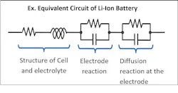
Li-ion battery impedance is commonly represented using equivalent circuit models consisting of:
- Ohmic resistance (Rs)
- Charge-transfer resistance (Rct)
- Double-layer capacitance (Cdl)
- Diffusion-related elements
Different frequency regions emphasize different electrochemical phenomena. High-frequency measurements are dominated by ohmic resistance and interconnect effects. Mid-frequency measurements reveal interfacial reactions and solid-electrolyte interphase (SEI) behavior. Low-frequency measurements capture diffusion processes and concentration polarization.
Because impedance characteristics vary with state of charge, EIS can also provide complementary information to traditional SOC estimation methods, particularly under dynamic operating conditions where OCV-based approaches become less reliable.
This separation of electrochemical phenomena is one of the primary advantages of EIS compared with conventional resistance measurements.
Visualizing Battery Behavior with Nyquist Plots
EIS results are commonly visualized using Nyquist, or Cole-Cole, plots, which graph the imaginary component of impedance against the real component (Fig. 2).
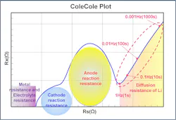
Changes in the shape of the plot will reveal valuable information about battery condition. The diameter of a semicircular arc is often associated with charge-transfer resistance, while shifts in the real-axis intercept can indicate changes in ohmic resistance. Distortions or movement of these features may signal evolving degradation mechanisms.
Rather than treating battery degradation as a single numerical value, EIS transforms impedance into a structured representation that can provide insight into interfacial reactions, diffusion behavior, and evolving degradation pathways.
How EIS Can Identify Lithium Plating and Run Safety Diagnostics
One of the most important applications of EIS is the detection of lithium-plating precursors. Lithium plating occurs when lithium insertion into the negative electrode becomes rate-limited and metallic lithium begins depositing on the electrode surface. One of the main risks comes from charging the battery in very cold temperatures, which can cause electrolytes to become thick and viscous, slowing down the movement of lithium ions. Under these conditions, the ions may fail to enter the anode and instead coat its surface as metallic lithium.
Cell aging can also increase the risk of lithium plating, as does aggressive fast charging or charging the battery cell very close to its maximum capacity.
The challenge is that lithium plating often develops before voltage abnormalities reveal themselves or capacity loss becomes obvious. Once established, it can lead to irreversible lithium loss, accelerated degradation, dendrite formation, localized heating, and ultimately increased thermal runaway risk.
EIS: Expanding the Safe Operating Area of Batteries
Electrochemical impedance spectroscopy (EIS) doesn't replace the measurement of DC cell voltages, pack currents, temperatures, and other operating parameters commonly used by a BMS. But it does reveal what those measurements can’t. With more data at its disposal, the BMS can monitor a battery’s condition more precisely, improving its safety, longevity, and performance.
EIS can, for instance, enable earlier detection of thermal runaway. A traditional BMS typically relies on thermistors or other temperature sensors distributed throughout the battery pack. But these sensors may detect abnormal heating only after a problem has already progressed significantly. Gas and pressure sensors can provide an additional warning when a cell begins to vent, but venting may occur only shortly before a battery fire. Both approaches are slow to react at the individual cell level.
Because battery impedance is highly sensitive to temperature, EIS can be used to estimate the core temperature of every cell, potentially detecting signs of thermal runaway further ahead of time.
EIS can also enable more frequent fast charging of batteries. High charging currents can accelerate cell aging and increase the risk of lithium plating, which occurs when lithium ions cannot diffuse into the cell quickly enough to accommodate the additional charge. Diffusion rates can vary with a battery's temperature, state of charge, and the age of its components.
EIS can monitor these conditions at the cell level, helping the BMS determine when charging conditions become unfavorable. It can then adjust charging rates to maintain the battery pack’s safety or adjust ambient temperatures using cooling fans or heaters. By responding to battery conditions in real-time, the BMS may be able to maintain higher charging currents for longer periods and even safely charge the battery closer to its max capacity.—James Morra
Because conventional BMS indicators may not detect these early-stage changes, EIS offers a potentially valuable diagnostic tool. Changes in phase behavior, impedance components, and charge-transfer-related features can reveal evolving interfacial conditions before more visible symptoms emerge.
Particularly in the mid- to high-frequency region, EIS measurements will provide useful information while maintaining practical measurement times suitable for field deployment.
EIS Implementation Challenges in a Commercial BMS
The benefits of EIS are well understood in the lab, where it’s widely used for testing new battery cells and evaluating new chemistries. But implementing it within production BMS hardware introduces significant challenges.
One of the biggest challenges is that battery-cell impedance is extremely small, often on the order of 1 mΩ, so it’s more difficult to measure accurately. Under typical excitation currents, resulting voltage changes may be only a few hundred microvolts (for reference, 100 µV equals 0.1 mV). To make the most of EIS, these signals must be measured accurately in environments containing switching noise, electromagnetic interference, temperature variation, and other disturbances.
Phase accuracy also becomes critical. Measurement performance depends not only on amplitude resolution, but also on timing synchronization, sampling precision, filtering characteristics, and signal-path matching. Practical deployment therefore requires careful consideration of measurement bandwidth, noise performance, implementation cost, and operating conditions.
Practical Approaches to Implementing EIS in BMS
Rather than attempting to miniaturize laboratory EIS instruments, some companies are aiming to extract useful impedance information using the resources already available within BMS architectures.
For instance, Renesas’ approach emphasizes low power consumption, minimal external components, and compatibility with high-voltage multi-cell battery systems. Two complementary techniques are employed:
Approach 1: AC Superposition with Lock-In-Equivalent Synchronization
The first approach introduces a small AC component into the battery current and extracts impedance information using synchronized measurement techniques (Fig. 3).
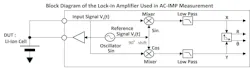
Traditional laboratory instruments often rely on multiple analog-to-digital converters (ADCs) and dedicated lock-in architectures. The Renesas approach seeks to achieve equivalent amplitude and phase extraction using practical BMS resources, including delta-sigma converters and digital processing.
This method is particularly effective during standby conditions where current flow is minimal and electrical noise is reduced (for instance, when a stationary energy storage system is idling or when an electric vehicle is parked). Controlled excitation and synchronized detection allow for stable extraction of impedance information while maintaining compatibility with production BMS requirements.
Approach 2: FFT-Based Estimation from Pulse Responses
The second approach to EIS leverages the mathematical relationship between time-domain and frequency-domain behavior.
Instead of performing direct frequency sweeps, voltage relaxation waveforms generated during normal BMS operation can be analyzed using FFT-based techniques to estimate equivalent RC parameters. These parameters are directly related to relaxation behavior associated with diffusion and interfacial reactions, making them relevant to charging control, thermal management, and degradation assessment.
Although challenges remain due to noise sensitivity and parameter correlation, this approach offers a practical path toward extracting EIS-related information from measurements already available within existing BMS workflows.
From Measuring Impedance to Using It to Improve Performance
The ultimate value of EIS lies not only in measurement, but also in transforming measurement results into actionable decisions.
In the lab, trained experts often interpret Cole-Cole plots visually. Production BMS implementations require automated judgment, robustness to variation, and explainable diagnostic outputs.
Consequently, impedance data must be converted into quantitative features suitable for automated analysis (Fig. 4). Examples include shifts in Rs, changes in arc diameter associated with charge-transfer resistance, and movement of impedance peaks.
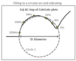
Renesas focuses on extracting stable diagnostic features using a limited number of frequency points, enabling practical implementation without requiring full-spectrum measurements. This approach supports rapid safety assessment while integrating measurement, analysis, and decision-making directly within the BMS.
The Time Has Arrived for the EIS-Enhanced BMS
As engineers lean harder on lithium-ion batteries everywhere from EVs to data centers, EIS conventional diagnostic approaches based solely on voltage, current, and temperature measurements are hitting their limits. EIS provides a richer view of battery behavior by separating electrochemical processes according to their characteristic time constants. This inside track helps identify battery degradation mechanisms and emerging safety risks.
By combining practical impedance measurement techniques, feature extraction, and automated decision-making, Renesas’ technologies provide a path forward for field-deployable EIS.
>>Download the PDF of this article
 dreamstime_dashark_351471872
About the Author
 Masaki Hogari
Masaki Hogari
Senior Principal Application Engineer, Renesas Electronics
Masaki Hogari is a Principal Application Engineer at Renesas Electronics and a member of the Algorithm Firmware Technology (AFT) team. He has extensive experience with lithium-ion battery technologies, and battery-management-system (BMS) solutions. His technical expertise includes battery-management algorithms for state-of-charge estimation, battery health diagnostics, impedance-based analysis, battery safety, and battery swelling detection.
His efforts have contributed to the adoption of lithium-ion battery technologies across a wide range of industrial applications, including power tools and e-bikes, and has led the development and commercialization of fuel-gauge IC solutions for several battery systems. He currently specializes in battery characterization and algorithm development and has a strong track record of driving innovation through patented technologies and enabling successful battery system deployments, which includes education and training across the globe.
 John Carpenter
John Carpenter
Director of Project/Program Design, Renesas Electronics
John Carpenter is a Director at Renesas Electronics with the role of System and Application Engineering for the Battery Management group. He has extensive experience focusing on system solutions in battery- and power-management technologies, leading complex product development programs and cross-functional teams. John specializes in project execution, stakeholder management, systems development, and strategic market planning, with a strong track record of delivering innovative solutions and driving organizational success through collaboration and operational excellence.
Comment About the Article
To join the conversation, and become an exclusive member of Electronic Design, create an account today!
 Leaders Logo
Leaders relevant to this article: