Reevaluating DC-Link Capacitors for SiC Inverters
What you'll learn:
- How the fast switching speeds and other characteristics of SiC devices create new challenges in DC-link capacitor design.
- Key parameters that need to be considered by electronics engineers when selecting DC-link capacitors for SiC inverters.
- The three types of capacitors used in EV traction inverters, and how they differ in performance, reliability, and durability.

Traction inverters sit at the heart of modern electric vehicles, converting the battery’s DC output into the AC power required to smoothly drive the motor. Maximizing the efficiency at which that happens is one of the major priorities for engineering teams. At the same time, teams have to look for ways to minimize the weight and cost of these inverters. These goals must also be balanced against the needs of thermal management, as reliable operation depends on not overloading the power electronics.
For decades, insulated-gate bipolar transistors (IGBTs) formed the foundation of EV inverter designs. But that’s started to change over the last decade with the rise of silicon-carbide (SiC) MOSFETs.
SiC transistors, due to the device physics involved, can switch significantly faster than traditional IGBTs while reducing switching losses. This means that an SiC inverter can achieve significant weight and power gains over IGBT inverters.
Consequently, system designers can shrink the size of magnetic components and implement a DC link of lower capacitance, cutting down capacitor size. The resulting reductions in cooling requirements and overall system size help improve vehicle efficiency, range, and packaging.
For years, high costs prevented the widespread adoption of SiC MOSFETs in EV traction inverters. However, the Tesla Model 3 disrupted the industry by launching with first mass-market SiC inverter, showing that SiC was becoming commercially viable for modern EVs. The price of a 150-mm SiC wafer — the largest single cost component in a SiC MOSFET — has fallen from approximately $1,200 in 2017 to about $700 in 2025.
The result was a rapid proliferation of SiC inverters, with significant year-on-year performance gains now being posted by engineering teams.
The DC-Link Capacitor Challenge in SiC Inverters
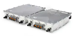
As a disruptive technology, SiC MOSFETs have introduced new system-level challenges for engineers. One of the most obvious is in capacitor selection for the DC-link stage between the battery pack and the inverter’s switching stage in the EV (Fig. 1). Through intermediate storage of electrical energy, DC-link capacitors play a key role in stabilizing the DC bus voltage supplied to the switches. And without a well-sized one, performance can take a hit.
As an electrical “buffer,” they compensate for instantaneous power fluctuations from an EV’s battery and maintain a constant voltage. Thus, DC-link capacitors are crucial in preventing sudden variations in AC voltage that can undermine the motor’s performance, stability, and lifetime. They also absorb AC ripple currents that would otherwise propagate back to the EV’s battery and cause electrical losses, overheating, and wear-and-tear.
The challenge of selecting DC-link capacitors for SiC inverters is that many capacitors traditionally used in IGBT-based designs aren’t suited to meet the heightened electrical and thermal demands placed on SiC inverters.
>>Download the PDF of this article, and check out the TechXchange for similarly themed articles and videos
SiC MOSFETs operate at faster switching speeds, resulting in higher ripple-current frequencies and steeper voltage transitions that place greater stress on the DC-link capacitor. At the same time, the higher power densities possible with SiC mean that thermal management is increasingly critical to overall system performance. Together, these factors are forcing many electronics engineers to rethink DC-link capacitor design, requiring a review of the basic parameters for these components.
Parameters to Assess When Choosing DC-Link Capacitors
Several key parameters need to be considered when selecting DC-link capacitors for SiC inverters:
- Equivalent series resistance (ESR): This indicates the internal resistance within a capacitor that causes electrical losses and overheating, which is especially relevant when subject to high-frequency or high-voltage ripple currents that encounter resistance. Measuring and minimizing the capacitor’s ESR is key to ensuring a capacitor’s thermal stability and overall lifespan in the face of high-frequency SiC inverters.
- Equivalent series inductance (ESL): This refers to the capacitor’s ability to respond to high-frequency current transients. So, capacitors with high ESL may not effectively suppress the voltage spikes generated during fast switching events. As a result, low-inductance capacitor designs are of primary importance in SiC inverter applications.
- Ripple-current capability: This indicates how much AC current the capacitor can safely handle without excessive temperature rise. Designers must ensure that capacitor’s ratings exceed the expected operating ripple current under worst-case conditions.
- Thermal characteristics: Temperature has a significant impact on capacitor aging and reliability. Designers will need to review a capacitor’s ambient operating temperature and how it will respond to temperature rises caused by ripple-current losses.
- Expected lifetime: Most traction inverters are required to have a system lifetime exceeding 10 years. To confirm that they can perform up to standard for the duration of the inverter’s design life, the capacitors will need to undergo lifetime modeling and reliability analyses.
- Layout and parasitic effects: Important layout considerations include minimizing loop inductance between capacitors and power-switching devices, keeping conductor length to an absolute minimum, and ensuring symmetrical current paths. Optimizing these and other factors, such as capacitor placement and busbar design, enables peak performance within minimal volume.
The Relevant Capacitor Technologies for SiC Inverters
Traditionally, aluminium electrolytic capacitors or Al-caps dominated DC-link applications. These capacitors offer a relatively large capacitance in a small volume, while remaining relatively low cost.
However, their ESR profile and lifetime performance are often inadequate for high-frequency SiC inverters. They’re prone to overheating, and they tend to degrade markedly over their lifespan as a result of thermal stress and demanding operating conditions. As a result, film capacitors have become the go-to for DC-link capacitors in high-performance inverters. They provide low ESR and ESL, along with high ripple-current capability.
In addition, they exhibit self-healing properties. While localized damage can occur due to imperfections in the film, mechanical stress, or overheating, this doesn’t result in catastrophic failure. Instead, a film capacitor’s total capacitance will be slightly reduced following an overload event. Though it can lead to eventual failure through repeated dielectric breakdown over time, film capacitors are resistant to initial overloading from one standalone event.
The main drawback with film capacitors is their larger physical dimensions compared to aluminium electrolytic capacitors. This can pose some challenges on the increasingly crowded circuits boards used in SiC inverters.
In the context of these packaging constraints, multi-layer ceramic capacitors (MLCCs) are also often used in DC-link applications. These devices offer very low ESR and ESL, making them highly effective at the higher switching frequencies of SiC. They’re also highly compact, so many of them can be packed together in a small volume, enabling very high power-density inverters that can fit into tight spaces inside EV traction inverters.
However, reliability remains their primary limitation. Ceramic capacitors are very brittle and prone to cracking due to vibration, PCB flexing, mishandled assembly, or thermal expansion. They also experience piezoelectric effects, where AC current causes the material to repeatedly expand and contract, creating audible noise at the switching frequency. The fragility resulting from these factors is reflected in the high cost of ceramic capacitors, which make them uneconomical as the sole type of capacitor in the inverter.
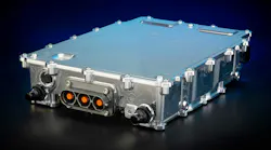
In practice, the optimal solution for many EV SiC inverters is a hybrid approach that combines film capacitors with a cluster of ceramic capacitors (Fig. 2). This allows engineers to balance cost, performance, packaging, and reliability. The exact ratio of film to ceramic capacitors will depend on the expectations and requirements of the final inverter and EV platform.
Applying the Full-System Perspective to SiC Inverters
Choosing a capacitor technology plays a key role in striking a balance of performance, efficiency, affordability, and power density in SiC inverters. However, engineering expertise and smart inverter system integration help ensure that it meets the rigorous demands of a modern EV. Proper system-level design, including layout optimization and a rigorous approach to thermal management, is equally important to reaping all of SiC’s benefits.
As SiC continues to mature, engineering teams are having to revisit their old assumptions. These old assumptions include their choice of materials for DC-link capacitors, as well as many traditional expectations about the inverters as a whole.
>>Download the PDF of this article, and check out the TechXchange for similarly themed articles and videos
About the Author

Hannah Ansell
Head of Electronics, Helix
Hannah Ansell is Head of Electronics at Helix. Hannah holds a Bachelor of Engineering (B.Eng. Hons), Electrical and Electronics Engineering from Northumbria University, and a Certificate in Management Studies from the University of Northampton.
Comment About the Article
To join the conversation, and become an exclusive member of Electronic Design, create an account today!

Leaders relevant to this article: