Bootstrapped Buck-Boost Converter Keeps LEDs on Longer
What you'll learn:
- How to extend battery life for LED strings using a buck-boost converter.
- Why bootstrapping the buck-boost converter offers a better option.
- Results of the bootstrapped converter setup.

Living on a country road has its advantages. It's peaceful and surrounded by nature. But it also has its drawbacks: frequent power outages. Losing electricity is common enough to be more than a slight inconvenience, especially in the evenings when the entire house is plunged into darkness. While most households can manage without internet service for a few hours, living without light is a different story.
My usual solution is to dust off an old LED lamp and load it with four fresh D-cell batteries, giving me a couple of hours of usable light. However, the batteries drain rapidly, and the lamp gradually grows dimmer until darkness once again takes over. So, after the most recent outage, I decided it was time to put my engineering background to work and develop a better solution. To make it produce more light for longer, I explored several approaches for driving the LEDs more efficiently.
After developing a design strategy and adjusting it to overcome the less-than-ideal design of the device, I landed on a circuit based on a buck-boost converter. The design also uses a bootstrapping technique to further improve efficiency, maximizing the useful life of both the batteries and the converter itself.
The Plan: Extending Battery Life with a Buck-Boost Converter
LEDs are typically wired in series and driven with a constant current source. The lamp’s internal architecture was anticipated to employ a similar series configuration, using a current-limiting resistor to regulate the LED string. During battery discharge, the declining supply voltage reduces the forward bias across the LEDs, resulting in diminished luminous output until the LEDs extinguish at their minimum operating voltage threshold.
Given all that, it would make sense to use a buck-boost converter to provide a constant voltage to the LED string, possibly limiting the current with a small resistor. This comes with another advantage: As the battery voltage slid below the bias voltage of the LEDs, the circuit would boost the battery voltage, thus keeping the LEDs illuminated.
The DC2119A, an evaluation board for the LTC3115-2 buck-boost converter, was selected for integration into the light’s enclosure. This device features a 40-V maximum input voltage, enabling extended operation under various supply voltage conditions, including emergency backup power scenarios. Figure 1 shows the internal power stage of the LTC3115-2.
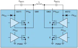
Notice that FETs A and B form a buck converter, with FET C being permanently off and FET D being permanently on. If PVIN is higher than PVOUT, a voltage is created across the inductor when FET A switches on, charging the inductor, with the current flowing from SW1 to SW2. Then, FET A switches off and FET B switches on. Current flows up FET B, enabling the inductor current to continue to flow from SW1 to SW2, and thus into the output capacitor connected to PVOUT.
In boost mode, FETs C and D oscillate in antiphase, with FET C charging the inductor from the input voltage and FET D discharging the inductor into the output capacitor. Thus, FET A is permanently on, and FET B is permanently off. In buck-boost mode, because the input voltage and the output voltage are the same, there’s no voltage across the inductor, so the switching strategy needs to change slightly. Figure 2 shows the switch node voltages and the inductor current when the input and output voltages are both at 6 V.

(FET A + FET C): FET A switches on and node SW1 rises to PVIN. FET C switches on and node SW2 is shorted to 0 V. This imposes a high voltage across the inductor and its current ramps linearly, flowing from SW1 to SW2.
(FET A + FET D): Then FET C switches off, causing a reverse voltage across the inductor as it tries to maintain current flow. This means node SW2 rises until the body diode of FET D starts to conduct, meaning that SW2 rises 0.6 V above PVOUT. Subsequently, FET D switches on, shorting out the body diode and the voltage at SW2 drops to PVOUT. The inductor current linearly decays, flowing into the output capacitor.
(FET B + FET D): Next, FET A switches off, causing a reverse voltage across the inductor; SW1 dips negative by 0.6 V as the body diode of FET B conducts. Then FET B switches on, shorting node SW1 to 0 V. Therefore, node SW1 is no longer at VIN but 0 V, so there’s a higher voltage across the inductor. As a result, the inductor discharges more rapidly.
(FET B + FET C): After that, FET D switches off, causing FET D’s body diode to conduct, pulling SW2 above PVOUT by 0.6 V. Then FET C switches on, pulling SW2 to 0 V. Thus, SW1 and SW2 are pulled to 0 V, allowing the flying capacitors, CBST1 and CBST2, to recharge. The voltage on these capacitors is used to high-side drive FETs A and D.
The New Plan: Bootstrapping the Buck-Boost Converter
In most cases, LEDs are wired in series. What I uncovered inside the lantern, though, is that all of the LEDs were wired in parallel and driven straight from the rechargeable battery pack via four huge 7.5-Ω, 3-W resistors that burned through the life of the battery. With all of the power dissipation caused by these resistors, it’s no small wonder that the batteries didn’t last long. The voltage across the LEDs measured 3.2 V.
Rechargeable batteries have a terminal voltage of about 1 V when completely discharged, meaning the lantern battery stack would decay to about 4 V. Thus, the buck-boost converter was selected, even though a simpler buck converter would be just as suitable.
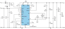
The large resistors were removed, and the LED string was powered directly from a bench power supply, which was then adjusted to get optimum brightness (about 3.3 V). Afterward, the output voltage of the LTC3115-2 was adjusted to 3.3V and connected directly to the LEDs. The design is outlined in Figure 3.
The battery pack was connected to the boost converter, and the LEDs lit up with full brightness as intended. This lasted about 10 minutes, after which the LEDs started to flicker. This was far-from-ideal performance.
It was found that the battery voltage was dipping below the input undervoltage-lockout threshold of 2.4 V, which was causing the part to reset. The part switched off, the LEDs extinguished, the load was removed from the battery, and the battery voltage increased. That, in turn, caused the part to restart and the LEDs to illuminate, so the entire process started over.
This is known as “motorboating.” The term comes from the early days of portable audio amplifiers that would slowly oscillate as the load was applied and removed from the battery, causing a pop, pop, pop sound (like a motorboat engine) on the loudspeaker.
This problem was alleviated by bootstrapping the VIN pin from the output voltage. Bootstrapping is a technique where the output voltage is used to power the input pin of a boost converter, usually to achieve higher efficiency due to the increased drive to the internal FETs (for more details, check out “More Bang for Your Boost: Driving Heavier Loads with Lower Battery Voltages”).
The datasheet goes into detail about bootstrapping the VCC pin to improve the converter’s efficiency by minimizing the voltage across the LTC3115’s internal low-dropout regulator (LDO). However, in this circuit, bootstrapping can also be used to keep the VIN pin above its undervoltage lockout and thus keep the device operating over a wider range of input voltages.
Consequently, the PVIN and VIN pins were driven separately, and the VIN pin was bootstrapped to VOUT using diode D2 in Figure 3. Since the output voltage is at 0 V on startup, an additional diode, D1, was also connected to VIN to ensure the part started up. Both diodes are 1N5819s.
An additional capacitor, C3, was added to keep the VIN pin high during temporary dips in the battery voltage. The current for the LTC3115’s power circuitry (the FETs and inductor) came from PVIN, meaning VIN’s current consumption is relatively light so that it can be decoupled with a moderately low-value capacitor. This technique vastly improved the operating performance of the LED driver and allowed the battery voltage to decay to a lower voltage.
To further explain the effect of bootstrapping, the waveforms in Figure 4 show what happened when a very old battery stack was used. PVIN is shown in yellow, VOUT in blue, and VIN in pink.
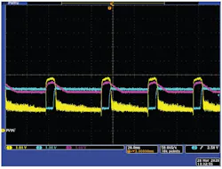
Just to the left of the center of the trace, the VOUT ramps up as the part starts up. This places a heavy load on PVIN, so PVIN starts to drop. The pink trace is measured across capacitor C3, which has been charged by PVIN to a voltage that’s a Schottky diode drop below PVIN. When PVIN starts to fall, VIN stays high, held up by capacitor C3, but discharges linearly due to the quiescent current of the LTC3115-2 (around 6 mA). When VIN falls below VOUT, D2 starts to conduct, thus holding VIN up even though PVIN has collapsed.
Finally, the battery has no more energy to give. At about 1.6 divisions from the center of the trace, the PVIN trace dips below 1.1 V, which is the threshold of the RUN pin and the part switches off. The load is removed from the battery, so PVIN rises and the process starts again.
The Final Results: A Power-Sipping Backup Light Source
Once fresh batteries were applied to the circuit, the LED performance was much more acceptable with consistent brightness. The circuit was then tested with a bench power supply that had both the original 7.5-Ω resistors and the buck-boost converter.
With the bench power supply set to 5.90 V, the input current with the resistor circuit was 320 mA and the resistors got considerably hot. With the LTC3115, the input current fell to about 160 mA, indicating a considerable reduction in battery current. Moreover, with the buck-boost converter circuit, when the input voltage fell, the LED brightness remained constant.
The LTC3115-2 helps to alleviate some of the pain caused by ongoing power outages experienced in a household. And when used with bootstrapping, it can extend the operating life of both the lantern and the buck-boost converter. While the circuit was developed primarily for the hobbyist, the techniques performed in this article can also apply to many industrial-grade systems that use a buck-boost converter to run on relatively low-voltage battery packs.
>>Download the PDF of this article
 dreamstime_ozgurguvenc_25416685
About the Author
Simon Bramble
Principal Applications Engineer, Analog Devices Inc.
Simon Bramble graduated from Brunel University in London in 1991 with a degree in electrical engineering and electronics, focusing on analog electronics and power. He has spent his career in analog electronics and worked at Maxim Integrated and Linear Technology (both now part of Analog Devices).
Comment About the Article
To join the conversation, and become an exclusive member of Electronic Design, create an account today!
 Leaders Logo
Leaders relevant to this article: