The Bandwidth Arms Race: Inside the Leap from PCIe Gen 6 to Gen 8
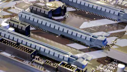
If the last decade of computing had a quiet revolution, it happened inside the connectors and signal traces not seen by end-users. Every AI accelerator, NVMe SSD, GPU, and modern network card depends on one unsung backbone: PCI Express. And just as the world was settling into the promise of PCIe Gen 5, the PCI-SIG has already pushed three new generations into view: Gen 6, Gen 7, and the brand-new Gen 8, which reached a Revision 8.0, Draft 0.5 specification dated April 23, 2026.
Together, they represent the most aggressive bandwidth scaling in PCIe's history. In just three steps, raw per-lane data rates quadruple, aggregate x16-class bidirectional bandwidth crosses the one-terabyte-per-second mark, and the physical layer pushes copper to a 64-GHz Nyquist frequency. Until recently, that territory looked like it would force a move to optics.
This article breaks down what changes between Gen 6, 7, and 8 — at the physical, data link, and transaction layers — and why these changes matter for the next wave of AI, high performance computing (HPC), and data center infrastructure.
Why Three Generations in Quick Succession?
The answer is simple: AI workloads broke the old roadmap.
Training large models, feeding GPUs, and scaling memory fabrics like CXL all hammer the interconnect in ways the original PCIe cadence (a new generation every 3–4 years) cannot keep up with. PCI-SIG responded by compressing the schedule — Gen 6 was finalized, Gen 7 advanced through its drafts, and Gen 8 already has a Draft 0.5 specification on the table. Each generation doubles per-lane bandwidth while preserving the things engineers care about most: backward compatibility, low latency, and reasonable power.
The Headline Numbers
At the heart of the comparison sits one chart that tells most of the story:
| Specification | PCIe Gen 6 | PCIe Gen 7 | PCIe Gen 8 (Draft 0.5) |
|---|---|---|---|
| Raw data rate per lane | 64 GT/s | 128 GT/s | 256 GT/s |
| Per-lane Nyquist frequency | 16 GHz | 32 GHz | 64 GHz |
| Unit interval (UI) | 31.25 ps | 15.625 ps | 7.8125 ps |
| x16-class bidirectional bandwidth | ~256 GB/s | ~512 GB/s | ~1024 GB/s * |
| Signaling | PAM4 | PAM4 | PAM4 |
| Flit / encoding | Flit Mode + FEC + 64-bit CRC | Flit Mode + FEC + 64-bit CRC | Unchanged — same Flit layout, FEC, and 64-bit CRC |
| First (raw) BER | 1e-6 | 1e-6 | 1e-6 (light-weight FEC + 64-bit CRC + link-level retry) |
| Max pad-to-pad channel loss | -32 dB @ 16 GHz | -36 dB @ 32 GHz | -36 dB @ 64 GHz |
| Tx equalization | 4-tap (C-2, C-1, C0, C-1) | 4-tap | 4-tap — unchanged from Gen 6/7 |
| Rx equalization | CTLE + DFE | CTLE + DFE | Reference CTLE + ADC-based FFE (48 post-cursor, 8 pre-cursor) + 1-tap DFE |
| Retimer need | Optional | Optional | Optional — reach without a retimer is held the same as Gen 4–7 |
| Low-power mode | L0p | L0p | LTSSM unchanged (L0p, L1, L2); no new low-power feature in Draft 0.5 |
| Headline new feature | Flit Mode | (Gen 7 additions) | Link Partitioning (x16 served as two x8 links at 256 GT/s) |
* On x16 bandwidth at 256 GT/s: the spec delivers full x16-class bandwidth by partitioning a x16 port into two independent x8 links (see "Link Partitioning" below), not by running a single x16 link. A single x16 link at 256 GT/s is, in fact, under strong consideration to be removed from the specification entirely.
Three things jump off this table:
- PAM4 signaling is here to stay. PCIe 6 introduced it; Gen 7 and Gen 8 don’t abandon it. Gen 8 runs PAM4 at a 64-GHz Nyquist frequency with a 7.8125-ps unit interval, leaning on the same equalization and FEC toolkit rather than a new modulation scheme.
- Continuity dominates: Gen 8 is more refinement than reinvention. The Flit layout, the FEC and CRC calculations, the replay mechanism, the loopback sequences, the 4-tap transmit equalization scheme, and the reference-clock requirements are all explicitly unchanged from Gen 7. First-pass BER stays at 1e-6, cleaned up by the same lightweight FEC, 64-bit CRC, and link-level retry. Even the channel budget holds: −36 dB at the new 64-GHz Nyquist and the maximum reach without a retimer is deliberately kept the same as Gen 4 through Gen 7. There’s no optical or silicon-photonics requirement in the draft, and no machine-learning-assisted equalization. The work of surviving 256 GT/s is done by a conventional (if aggressive) ADC-based receiver and tighter jitter budgets.
- The one genuinely new structural idea is Link Partitioning. Rather than build an impractically wide x16 controller for 256 GT/s, two link partners can negotiate to split a x16 port into two independent x8 links. This is the headline change in Gen 8, and the spec openly weighs making it the only path to full bandwidth at the top speed.
What's Actually Changing Inside the Physical Layer?
The Gen 8 draft reuses far more of the Gen 7 physical layer than a casual reader might expect. However, it adds one substantial new mechanism and a fresh set of electrical targets for 256 GT/s.
The electrical headline is straightforward. Gen 8 runs at 256 GT/s using PAM4 at a 64-GHz Nyquist frequency, with a unit interval of 7.8125 ps. The maximum first-pass bit error rate (before burst-error correction) is held at 1e-6, the same target as Gen 6 and Gen 7, and it’s cleaned up by the same lightweight FEC, 64-bit CRC, and link-level retry.
The maximum pad-to-pad channel loss is −36 dB at 64 GHz — numerically the same budget Gen 7 allowed at 32 GHz — and the maximum reach without a retimer is explicitly kept the same as Gen 4 through Gen 7. Transmitter and reference-clock jitter limits do tighten: The main transmitter jitter terms are roughly half their Gen 7 values.
The transmitter keeps the familiar 4-tap equalizer (two pre-cursor coefficients C−2 and C−1, one main cursor C0, and one post-cursor C+1) unchanged from Gen 6/7. On the receive side, the reference design is an ADC-based architecture: a reference CTLE with a DC-gain range of −15 dB to 0 dB, a feed-forward equalizer with 48 post-cursor and 8 pre-cursor taps, and a single-tap DFE, with the constraint h1/h0 < 0.5 to limit DFE burst errors.
For a channel to be compliant at 256 GT/s, the spec calls for a top eye height of at least 10 mV and a top eye width of at least 0.10 UI (0.78125 ps) at a BER of 1e-6.
The genuinely new structure is Link Partitioning, and it shows up right in the link-training handshake. A 2-bit Link Partition Control (LPC) field has been added to the EFM_CNTL1 symbol of the TS1 ordered set:
- 00b — the port intends to operate at ≤ 128 GT/s; Link Partitioning isn’t required.
- 01b — the port intends to operate at ≥ 256 GT/s and is capable of Link Partitioning.
- 10b — the port intends to operate at ≥ 256 GT/s and is invoking Link Partitioning.
- 11b — Reserved.
The two link partners exchange LPC values in Configuration.Linkwidth.Start (once Flit_Mode_Requirements_Met is set), and if partitioning is needed, it happens on the transition to Configuration.Linkwidth.Accept. Retimers must observe the LPC field on both pseudo-ports and follow whatever partitioning occurs, but they don’t influence the outcome of the negotiation. Partitioned links share the same sidebands (no sideband duplication), and the mechanism is orthogonal to the link-subdivision schemes in form-factor specs such as CEM and M.2.
Data Link Layer: A Deliberate Non-Event
PCIe Gen 6 was the generation that fundamentally re-architected the data link layer around Flit Mode — fixed-size flits with FEC and a 64-bit CRC, replacing the variable-length packet stream of every prior generation. Gen 7 refined how transactions are packed into those flits.
Gen 8's data link story is, by design, a non-event. The Flit layout, the FEC and CRC calculations, the rules for packing TLP bytes into a flit (TLPs per Half Flit), and the replay mechanism are all explicitly unchanged from Gen 7. Loopback sequences remain unchanged as well.
This freeze is intentional, and it points to the real engineering problem. To saturate a 256-byte-wide data path (per direction) clocked at 2 GHz — what it takes to feed a x16 link at 256 GT/s — a controller working against 64-byte cache lines or 32-byte DRAM accesses would need multiple simultaneous accesses in a single clock cycle while still honoring PCIe's ordering rules.
By keeping the upper-layer machinery fixed, PCI-SIG keeps Gen 8's entire engineering budget focused on that problem, which is exactly what Link Partitioning is meant to relieve.
Transaction Layer and Config Space: New Capabilities for 256 GT/s
The configuration-space changes in Gen 8 follow the same pattern set by earlier generations: A new speed gets its own extended capability, plus a sweep of updates to the fields that enumerate data rates.
For Gen 8 that means a new Physical Layer 256.0 GT/s Extended Capability, mirroring the per-speed capability structures earlier generations defined, along with updates to every configuration field referencing a data rate so that 256 GT/s can be advertised and selected. The Data Rate Identifier and the other data-rate references in the physical-layer chapter (Chapter 4) are updated for 256 GT/s, and the draft adds 256-GT/s compliance patterns and a 256-GT/s EIEOS for link bring-up and testing.
For firmware and enumeration code, the practical takeaway is the familiar one: Software written for Gen 5-era speed vectors will need to learn about the new 256-GT/s data rate and the new capability structure before it can correctly enumerate a Gen 8 device.
What Gen 8 Tells Us About the Future
Because it’s only a Draft 0.5, Gen 8 still has open questions. Nonetheless, the contours are already clear, and they look different from the optical-transition story that's sometimes told about it.
The dominant theme is continuity. The Flit format, FEC, 64-bit CRC, replay, equalization scheme, loopback sequences, and reference clock are all carried forward from Gen 7. The channel is still electrical: the same -36 dB loss budget (now measured at 64 GHz) and the same maximum reach without a retimer that was allowed by Gen 4 through Gen 7.
There’s no optical or silicon-photonics requirement in the draft, and no machine-learning-assisted equalization. The heavy lifting is done by a conventional ADC-based receiver (a 48+8-tap FFE and a single-tap DFE behind a reference CTLE) and by tightened jitter budgets.
The real new idea is structural rather than physical. Gen 8's answer to feeding a 256-byte data path at 256 GT/s is Link Partitioning. Rather than build a single, monstrously wide x16 controller, two link partners negotiate to split a x16 port into two independent x8 links, each running at 256 GT/s. The draft openly floats removing support for a single x16 link at 256 GT/s altogether, in which case two-x8 partitioning would become the only way to reach full x16-class bandwidth at the top speed. Concretely, the spec defines two capabilities:
- Capability A (full-width x16 at 256 GT/s) is optional and marked "under strong consideration to be eliminated."
- Capability B (partition into two x8s) is mandatory for any device that supports 256 GT/s.
One thing that doesn’t change is backward compatibility. Support for 256 GT/s implies support for every lower data rate, and a x16-capable device still trains as a single x16 link whenever its partner tops out at 128 GT/s or below. A Gen 8 slot will still happily accept a Gen 3 card. That promise, more than anything, is what keeps PCIe at the center of the industry.
Closing Thoughts
The leap from PCIe Gen 6 to Gen 8 is less a reinvention than a relentless tightening of the same screws: the same PAM4 signaling, the same Flit/FEC/CRC machinery, the same equalization scheme and reference clock, pushed to 256 GT/s and a 64-GHz Nyquist frequency. What's genuinely new is the structural move — Link Partitioning — that lets very wide links reach the top speed without an impractically wide controller, and the open question of whether a single x16 link survives at 256 GT/s at all.
For system architects, the near-term homework isn’t so much about exotic optics; it’s more about planning for partitioned links, ADC-based receivers, and the tighter jitter and channel budgets that’s demanded by 64 GHz. For software and firmware teams, the new Physical Layer 256.0 GT/s Extended Capability and the updated data-rate fields mean that PCIe enumeration code written for Gen 5 will need real attention.
PCIe is no longer just the bus that connects components inside a server. It’s becoming the fabric of the AI era. And Gen 6, 7, and 8 are the three steps making that fabric possible.
About the Author
 Shashank Chourasia
Shashank Chourasia
PCIe Solutions Architect | Director, Technical Marketing, Logic Fruit Technologies
Shashank Chourasia is a seasoned semiconductor professional with extensive experience driving PCIe and FPGA-based solutions across high-performance computing and embedded systems domains. He has proven expertise in technical marketing, solution architecture, and customer engagement, with a strong foundation in digital design and verification methodologies. Shashank is skilled in PCIe architecture, semiconductors, FPGA design, VHDL, Verilog, SystemVerilog, and design engineering, with a track record of leading cross-functional teams and delivering complex technology solutions from concept to deployment.
Shashank has a strong leadership background in program and project management, combined with deep technical acumen in VLSI and hardware acceleration technologies. He holds a PG Diploma in VLSI from Centre for Development of Advanced Computing (C-DAC).
LinkedIn : https://www.linkedin.com/in/shashank-chaurasia-4710aa18/
Comment About the Article
To join the conversation, and become an exclusive member of Electronic Design, create an account today!
 Leaders Logo
Leaders relevant to this article: