Is Power Electronics Outgrowing the Shunt Resistor?
What you'll learn:
- The hidden costs of shunt resistors as current levels increase and form factors shrink amid the industry’s shift to 48-V power: heat, size, and the need for a supporting cast of amplifiers, resistors, and filters.
- When it’s appropriate to adopt magnetic current sensors as an alternative and what thermal and isolation benefits designers can expect.
- Explore the attributes of magnetic sensing, including thermal and galvanic isolation advantages, that are inherent in coreless field sensors, Hall-effect sensors and advanced tunnel-magnetoresistance (TMR) sensors.
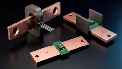
The shunt resistor has long been the cornerstone of current sensing. It's the first tool that electrical and electronics engineering students learn about, grounded in the elegant simplicity of Ohm's Law. For many applications, especially those below 100 V, the shunt resistor has been the default. It’s understood, and it works.
But the systems we design today aren’t the systems of a decade ago. The relentless drive for more power in smaller spaces, in everything from 48-V data center cooling fans and robotics to battery-powered tools and e-bikes, is pushing the classic playbook to its breaking point. And as switching frequencies climb into the megahertz range with the adoption of gallium nitride (GaN) and silicon carbide (SiC), engineers are finding that the “simple” shunt is forcing them into increasingly painful compromises.
The good news: the current sensing toolkit has expanded significantly. Today’s designers have access to a full range of magnetic-sensing technologies ranging from integrated conductor Hall-effect current sensors to coreless sensing to advanced tunnel magnetoresistance (TMR). Each one is optimized for different design priorities. The question is no longer whether to use a shunt or not. Instead, it’s “what’s the right current sensor for this specific job?”
The Hidden Complexity of Shunt-Based Current Sensors
The shunt has always been favored for its directness: pass current through a known resistance value, measure the voltage drop, apply Ohm's Law. For low-voltage, low-current applications like a simple 12-V, 1-A design where layout space and switching frequency aren’t constraints, shunts remain perfectly valid. But as current levels rise and form factors shrink, its directness comes with hidden costs, and they compound in ways that can surprise even experienced designers.
Heat is the shunt's most fundamental limitation. Power loss is governed by P = I2R, so as current increases, the heat dissipated by the resistor increases quadratically.
In a compact motor drive running 30 A RMS through a standard 1-mΩ shunt, the resistor alone dissipates almost 1 W of heat. That may seem manageable in isolation. But multiply it across a system such as hundreds of fans cooling an AI server rack, and the waste heat becomes a major contributor to the very thermal problem the system is trying to manage.
The size of the current sensor follows from heat. To lower resistance and reduce power loss, shunt resistors must get physically larger. More metal, more surface area, and more board space is the result. In a 48-V brushless motor drive for a humanoid-robot joint, that real estate is precious.
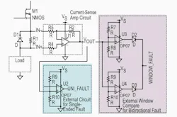
Then there’s the supporting cast of components. A shunt resistor is never the whole solution. It requires a precision amplifier, input filtering to suppress the parasitic inductance that creates voltage spikes at high switching frequencies, and a carefully designed Kelvin-connected layout to ensure the measurement isn’t corrupted by trace resistance. This ecosystem of parts consumes significant PCB real estate.
The industry's shift to 48-V systems, spanning from hybrid electric vehicles to AI server racks to autonomous robots, exposes another weakness. Placing a shunt on a 48-V rail requires a costly, 48-V-capable amplifier. This is particularly challenging in direct in-phase motor current sensing.
In such applications, the measurement node swings from ground to the full supply voltage with every commutation cycle. These aggressive common-mode transients (dv/dt) can overwhelm standard amplifiers, leading to corrupted measurements and pulse-width-modulation (PWM) blind spots.
What started as a simple shunt suddenly requires an expensive, high-performance system just to maintain signal integrity.
Changing the Game: Integrated Magnetic Current Sensors
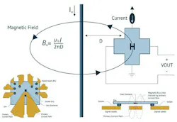
Rather than optimizing around the shunt's limitations, a fundamentally different approach has emerged: Measuring the magnetic field produced by every current-carrying conductor (Fig. 1).
The current runs directly through integrated magnetic current sensors. The conductor is integrated with the magnetic-sensing element and all of the signal conditioning in a single, factory-calibrated package. Where a shunt-based solution requires a resistor, an amplifier, filtering components, and a carefully designed Kelvin layout, the integrated magnetic sensor consolidates all of it with a single component.
The thermal advantage is significant. Because the sensor measures a magnetic field rather than a voltage drop across a resistive element, the internal conductor can have extraordinarily low resistance; in some cases, as low as 50 µΩ. In a 100-A system, this reduces sensing-related power loss by up to 90% compared to a typical 0.5-mΩ shunt. Less heat means smaller thermal solutions, longer component life, and the freedom to push power density higher without burning through the system's thermal budget.
The galvanic-isolation advantage is equally significant. Because the magnetic-sensing element has no electrical connection to the current-carrying conductor, these sensors are inherently immune to the high common-mode voltages that plague shunt amplifiers on 48-V rails or swinging motor phases. No specialized amplifier or complex common-mode rejection design is needed; the physics of the measurement simply sidesteps the problem.
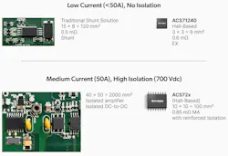
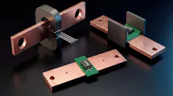
For currents up to approximately 200 A, these integrated solutions have matured into drop-in replacements that are smaller, cooler, and more robust (Fig. 2). The footprint reduction can be striking — in some cases occupying 95% less board space than a discrete shunt solution.
Scaling Up: Coreless Sensing for High-Current Systems
As systems push beyond 200 A into the territory of EV inverters, power distribution, and high-density data center power, even the ultra-low resistance of an integrated conductor can cause heat to start building. Historically, this was the domain of core-based field sensors — devices that use a bulky C-shaped magnetic concentrator physically placed around a busbar.
Modern coreless solutions have changed the equation. These advanced sensors sit directly over a PCB trace or busbar and measure the magnetic field without any physical contact or concentrator. The ability to sense hundreds or even thousands of amps flowing through an unbroken conductor provides design flexibility in power-dense applications, like in the interior of an AI server power-supply unit, where vertical clearance matters.
The tradeoff, traditionally, has been noise. Without a core to concentrate and amplify the magnetic field, the sensing element works with a much weaker signal. For Hall-effect sensors, this can limit the dynamic range and resolution, particularly at lower current levels within a high-current system. It's a physics problem: The Hall element produces a tiny, microvolt-level signal that requires significant amplification, and that amplification inevitably brings noise along for the ride.
The Quantum Leap in Current Sensing: TMR Technology
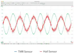
New innovations in current sensors are where the noise problem finds its solution. One of these technologies is TMR, which measures the magnetic field with a massive change in electrical resistance caused by electrons quantum-tunneling through an ultra-thin insulating barrier. The signal that comes out of it is orders of magnitude stronger than anything a Hall element can produce (Fig. 3).
This fundamental difference has multiple advantages:
- Noise: Because the TMR signal starts out strong, it requires much less amplification. Less gain means less noise. While traditional Hall-based sensors often struggle with a noise floor around 40 mA RMS, TMR-based sensors can achieve below 10 mA RMS.
- Resolution: This improvement delivers signal-to-noise ratios that approach shunt-class performance, enabling high-fidelity measurement across the full dynamic range of the system without the thermal penalties of a resistor.
- Speed: The adoption of GaN and SiC is pushing switching frequencies well above 1 MHz. At these speeds, legacy current sensors will struggle to keep up. TMR-based sensors can break through these bandwidth limitations, with production devices now operating at 1 MHz, and an industry-first 10 MHz. This allows systems to detect overcurrent faults in 50 ns — fast enough to protect expensive wide-bandgap switches.
Current Sensors: The Critical Link in a Long Signal Chain
In any modern power converter or motor drive, the sensor is one part of a critical control loop. The sensor provides high-fidelity feedback, while the gate driver or motor controller in front of the power switch acts on it. As switching frequencies increase, the traditional approach of optimizing each component independently gives way to a system-level perspective. Here, the sensor's bandwidth, latency, and noise floor must be co-designed with the driver's propagation delay and timing precision.
Engineers who think in terms of the complete "sensing to switching" signal chain, rather than individual components, can achieve better results (Fig. 4). This is particularly true in tightly packed, robotics joints where sensors and drivers stay coordinated, or AI server power supplies where nanosecond-precision measurement feeds directly into gate-drive decisions.
Despite that, the signal chain can only perform as well as the current-sensing technology at its front end. Integrated conductor sensors have eliminated thermal and complexity penalties for mid-range currents. Coreless sensors have made high-current measurement practical without bulk. And TMR technology has closed the noise gap that once kept engineers tethered to shunt resistors.
This evolution is giving engineers access to a wider range of current sensors that can fit their specific needs for form factor, bandwidth, accuracy, isolation, and power. Companies like Allegro MicroSystems have built comprehensive portfolios that span from 5 A to over 4,000 A, and from DC to 10 MHz. The tools are now here to tone down the tradeoffs of legacy current sensors.
>>Download the PDF of this article
 promo
promoAbout the Author
Matt Hein
Business Line Director of Current Sensors, Allegro MicroSystems
Matt Hein serves as the Business Line Director for Current Sensors at Allegro MicroSystems, where he leads the charge in revolutionizing magnetic current sensing. With a career in semiconductors spanning over a decade, Matt’s expertise bridges the gap between complex magnetic sensing and practical motor-driver applications. Known for his mission to make “V = I × R obsolete," Matt is dedicated to pushing the boundaries of what is possible in current sensing, bringing a wealth of technical knowledge and a passion for innovation.
Comment About the Article
To join the conversation, and become an exclusive member of Electronic Design, create an account today!
 Leaders Logo
Leaders relevant to this article: