Smart Power for Agile Robots: Integrated Motor Control, Thermal Management, and Energy Flow
What you’ll learn:
- Learn how to design compact, thermally sound robotic joints by managing motor power, regenerative energy, sensing, and control with integrated motor-control platforms.
- Learn how sensing, regenerative-energy management, and power-stage design interact in compact robotic joints.
- Discover how integrated motor-control devices can reduce PCB area and design complexity while supporting precise, efficient motor control.

Robots are becoming smaller, lighter, and more agile, while also moving faster, handling heavier payloads, and running longer on constrained power budgets. That combination forces designers to squeeze motor control and power electronics into tight spaces where every watt, square millimeter, and degree Celsius matters.
In practice, engineers must solve a set of power-management problems inside each joint or manipulator and still ship a system that’s reliable, certifiable, and easy to scale across a product family.
Why Powering Robotic Motors is so Challenging
Inside a typical joint, the actuator almost never runs at steady load. The joint must accelerate hard, hold near stall, then brake regeneratively, often repeating that pattern many times per second. Each phase stresses both the motor and the power stage in different ways; therefore, the power architecture needs to satisfy several conflicting demands at once.
High peak torque is needed in a compact joint with strict thermal limits, low-ripple torque and precise low-speed positioning, efficient use of energy including safe handling of regeneration, and protection and diagnostics that don’t consume PCB area or firmware time. Traditional multi-IC motor-control solutions can hit those targets, but growing integration pressure and tighter certification regimes make them progressively harder to manage.
As mechanical size and weight are reduced, the motor and gearbox are likely eliminated, resulting in the adoption of a frameless, direct-drive motor that shares the robot’s bearings. Stiffness is gained and backlash is diminished, which is good for positioning, but copper and iron losses become concentrated in a smaller volume and raise torque density. Stall torque becomes a thermal limit rather than simply “the torque needed to stop the motor,” and it typically sits well below the peak torque that marketing would prefer to quote.
High peak current during acceleration and holding torque at extreme joint angles both add significantly to heating, even if the average mechanical power looks modest. The joint structure itself becomes part of the heatsink, so control electronics must coexist with the motor’s thermal environment rather than sitting in a cool, remote cabinet.
Once the electronics and the motor are placed in the same confined space, the inverter’s own switching and conduction losses further load the thermal budget. The motor, inverter, and mechanics can no longer be placed as separate blocks. They have to be viewed as a single thermal system whose limits are set by temperature rises over a full motion cycle.
Challenge 1: Power Density and Thermal Limits in Robot Joints
Shrinking a joint usually starts with the mechanical envelope, which then pushes the consequences into the motor and power stage. When the frame and gearbox are eliminated, convenient surfaces for heatsinking have been removed and make it harder to spread losses. The copper and iron losses from a high-torque frameless motor now occupy a small volume directly under the control PCB.
In compact robotic joints, thermal capacity constrains sustained stall torque alongside the motor’s electromagnetic design. High current during rapid acceleration heats the windings and inverter, while sustained holding torque at unfavorable joint angles can produce prolonged temperature rise. The joint housing, bearings, and mechanical structure form part of the heat-transfer path, so power-device selection, gate-driver layout, and connector design can influence motor temperature.
When the motor and inverter occupy the same joint enclosure, inverter switching and conduction losses contribute to the joint’s overall thermal load. Motor, inverter, and mechanical design therefore require coordinated evaluation.
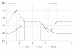
A practical design process evaluates torque and power profiles over representative motion cycles rather than relying solely on single-point ratings. The analysis includes inertial and gravitational torque components, acceleration and deceleration phases, and operating conditions in which peak current or prolonged holding reduces thermal margin.
For example, a 0.3-m arm lifting a 2-kg payload through 0.15 m in just over a second, pausing, and returning for the next part every few seconds provides a motion profile (Fig. 1) for evaluating peak power, average power, and accumulated heating. Such cycles can produce relatively low average power while imposing substantial peak-power demands and thermal stress.
Challenge 2: Accurate Current and Voltage Sensing in Compact Robots
High-performance field-oriented control requires accurate current and voltage measurements synchronized with pulse-width modulation (PWM). Measurement accuracy must be maintained despite high rates of current change, switching noise, and constrained PCB layouts.
In a compact joint, the available board area must accommodate power devices, gate-driver traces, sense resistors, amplifiers, filters, and the microcontroller or control core. Limited routing space and parasitic impedances complicate phase-current measurement across a wide dynamic range. Fast overcurrent detection is also necessary to protect the motor and power stage.
Temperature and DC-link voltage measurements must remain stable despite ground bounce and switching noise because these measurements support thermal management and protection algorithms. Measurement errors may cause nuisance trips or allow overstress to go undetected. At the same time, requirements to reduce component count and board area place constraints on discrete amplifiers, comparators, and filters.
Changes in power-stage topology or bus voltage may require renewed qualification of gate-drive behavior and protection thresholds, increasing development effort and risk.
Regenerative Energy and DC-Link Management in Robotic Arms
Frequent joint acceleration and deceleration transfer energy between mechanical and electrical forms. When an arm lowers a load or decelerates, the motor can operate as a generator and return energy to the DC link. The power architecture must accommodate this energy by returning it to the main bus, storing it locally, or dissipating it in a braking resistor, subject to the system’s thermal and safety limits.
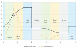
Regenerative-energy management begins with an analysis of torque and speed profiles and their relationship to mechanical power and DC-link transients (Fig. 2). Capacitor values, braking-resistor ratings, and protection thresholds are then selected to maintain acceptable bus voltage during typical operation and credible worst-case cycles. This analysis requires consideration of both joint-level behavior and the wider power system rather than individual component ratings alone.
Power-Stage and MOSFET Choices for 48-V Robotic Systems
A 48-V bus is used in many robotic systems to balance power delivery, current levels, and system requirements. At this voltage, MOSFET selection, gate-drive strategy, and PCB layout remain important factors in controlling switching losses, electromagnetic interference (EMI), and heat.
Discrete MOSFETs and gate drivers provide layout flexibility, while more integrated power stages may simplify implementation and improve consistency across designs. The appropriate approach depends on electrical, thermal, qualification, and manufacturing requirements.
In a compact robotic joint, MOSFET packaging, heat-transfer paths, and gate-drive tuning interact with the motor characteristics and motion profile. Switching-frequency selection involves tradeoffs among switching losses, current ripple, filtering requirements, and control performance. The selected operating point must satisfy both the thermal limits and the current-sensing requirements of field-oriented control. Reusing characterized power-stage building blocks can improve consistency across product variants compared with developing a separate discrete implementation for each robot.
Circuit simulation supports the evaluation of MOSFET technologies, gate-drive strategies, and switching frequencies before hardware fabrication. Representative motion cycles can be used to assess acceleration, holding torque, regenerative braking, and current-loop behavior.
These simulations provide a basis for comparing switching losses, conduction losses, DC-link ripple, and transient thermal stress across device options. In compact joints, changes in switching behavior or thermal impedance can materially affect continuous torque capability and reliability.
Motor-control development tools can complement this process through graphical configuration, parameter monitoring, and rapid evaluation. These tools allow engineers to test operating conditions without first developing a complete application firmware framework. Used alongside circuit simulation and hardware validation, they’re able to reduce development effort and help identify efficiency, EMI, and thermal issues earlier in the design process.
System-Level Considerations for Robotics Power Design
Motor power management in robotics involves coupled thermal limits, sensing requirements, regenerative behavior, EMI, and protection mechanisms. Changes in one area can affect performance or operating margins elsewhere. A coordinated design process begins with representative torque and power profiles and uses them to define the sensing architecture, heat-transfer paths, and power-stage requirements.
This approach supports the development of compact joints that meet temperature limits and dynamic-performance targets. Reusable motor-control building blocks may also support multiple robot configurations and payload options. The extent of reuse, firmware modification, and additional qualification depends on the electrical, mechanical, and safety requirements of each configuration.
Integrated Motor-Control Drivers for Robotics
Integrated motor-control devices can combine a microcontroller, gate drivers, power management, and a configurable analog front end (AFE) in a single package for field-oriented control.
Some devices include a high-performance microcontroller core, e.g., a 150-MHz Arm Cortex-M4F with floating-point support and hardware arithmetic acceleration. Such a core can execute field-oriented-control calculations alongside application and communications tasks, depending on the implementation and processing load.
An integrated AFE could include three precision differential programmable-gain amplifiers (PGAs), dedicated overcurrent comparators, and digital-to-analog converters (DACs) for programmable protection thresholds. This arrangement will support fast and filtered overcurrent protection while reducing the need for external amplifiers and comparators. Additional single-ended PGAs may support temperature and DC-link voltage measurements.
Integration can reduce PCB area and the number of external circuits requiring selection, layout, and validation (Fig. 3). Consolidating analog signal conditioning, gate-drive circuitry, and power management may also improve implementation consistency across projects. An AFE motor driver used with an existing microcontroller can provide similar consolidation without requiring migration to a different processor architecture, although interface and protection changes may still require firmware updates and validation.
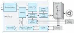
Digital peripherals may include multiple simultaneous sample-and-hold channels connected to a successive-approximation-register (SAR) analog-to-digital converter (ADC). Depending on the device, sampling rates of several million samples per second support synchronized current measurements for control and protection. Motor-control peripherals may also include 16-bit PWM units with interlock and dead-time functions, together with a quadrature encoder interface.
These resources support sensored or sensorless control implementations when combined with the appropriate algorithms and sensing hardware. On-chip interfaces such as CAN and SPI can reduce external interface requirements, although external transceivers may still be necessary.
Integrated low- and high-side gate drivers are able to directly drive external inverter MOSFETs through low-resistance totem-pole output stages. An internal power-management block may supply internal rails, control a buck or SEPIC converter, and provide bootstrap clamping and voltage supervision.
Consolidating gate drivers, precision amplifiers, comparators, DC-DC control functions, and voltage supervisors into a characterized IC can reduce external component count and simplify parts of the design and validation process. Overall qualification remains dependent on the complete system.
For designs based on an established microcontroller platform, an AFE motor driver provides an alternative to a fully integrated controller. A three-phase driver of this type can combine power-management and AFE functions while leaving control processing to an external microcontroller. Depending on the device, features may include a wide input-voltage range, a buck controller supplying the gate drivers and internal regulators, and a second buck stage providing a regulated supply for the external microcontroller.
These devices may also incorporate differential and single-ended PGAs, fast overcurrent comparators, DAC-programmable thresholds, cycle-by-cycle current limiting, and voltage or temperature lockout. SPI commonly provides configuration and status communication, while operating modes such as hibernate, brake, and driver disable support system-level power management and fault handling. Analog outputs and fault, reset, and clock connections allow the external microcontroller to interface with the driver while retaining the existing processor platform and toolchain.
This architecture consolidates analog and gate-drive functions, with the required firmware changes determined by the selected device and system implementation.
>>Download the PDF of this article
 promo
About the Author
 Jonathan Dodge
Technical Contributor, Qorvo Inc.
Jonathan Dodge, P.E., is a technical contributor for Qorvo. He spent 10 years working with SiC JFETs in circuit breaker and switch-mode applications, and developed online calculator and simulator tools for each. Other experience includes design of analog, digital, and power electronics, working with power levels ranging from 1.5 kW to 500 kW in renewable energy and other applications.
Jonathan received BSEE and MSEE degrees from Oregon State University and The University of Idaho, respectively. He’s a licensed professional engineer in the state of Oregon.
Comment About the Article
To join the conversation, and become an exclusive member of Electronic Design, create an account today!
 Leaders Logo
Leaders relevant to this article: