Efficient Power Conversion from an Intermediate Voltage Rail
What you'll learn:
- Why conventional buck converters can struggle with high step-down non-isolated DC-DC conversion.
- How hybrid converter topologies can improve efficiency using charge-pump-assisted buck regulation.
- Where hybrid topologies outperform transformer-based and traditional non-isolated bus converters.

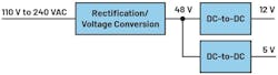
Different types of switch-mode power-supply topologies can convert an intermediate voltage rail into lower voltages used to power the various loads in a system. If the intermediate voltage is relatively high, e.g., 48 V, and the output voltage needs to be relatively low, e.g., 12 V or even 5 V, existing intermediate bus converter (IBC) topologies can be less than ideal. However, new innovations such as “hybrid converter” architectures may be able to offer higher conversion efficiency than simple heritage buck regulators.
The Challenges of High Step-Down DC-DC Conversion in 48-V Systems
DC-link voltages are employed in many systems. Often these voltages are 24 V, as in the industrial sector, or 48 V, as in the automotive sector. Modern data-center power architectures also use 48 V and, in some cases, 52 V, though several companies are upgrading to bus voltages as high as 800 V to help distribute power to AI server racks more efficiently. Different voltage-converter topologies can be utilized to step down the DC-link voltage to 12 V or 5 V.
Using the buck control concept to convert voltages from high to low is a common approach as long as no galvanic isolation is required for protection against electric shock or other reasons. However, a buck regulator tends to be only moderately efficient when converting a high DC-link voltage, such as 48 V, down to a low output voltage of 12 V or 5 V. As depicted in Figure 1, this is due to the necessary operation at a low duty cycle of 9.6%.
With a transformer-based architecture, such as a push-pull or forward converter, the duty cycle can be adjusted by the winding ratio of the transformer. That allows the conversion to take place more efficiently. The drawback, however, is that the transformer itself introduces additional power losses. Therefore, it’s often preferable to eliminate the transformer altogether, particularly in applications that don’t require galvanic isolation.
>>Download the PDF of this article
The Hybrid Converter Topology: Combining a Charge Pump and a Buck Regulator
One of the potential solutions to this dilemma lies in the concept of the hybrid converter. This innovative approach to power conversion connects a charge-pump topology to a step-down buck regulator. The converter uses a total of four switches that are used to halve a supply voltage with charge-pump action. In addition, the lower two switches are used together with an inductor to convert the halved supply voltage to the desired output voltage. Figure 2 outlines the hybrid voltage converter at a circuit level.
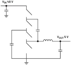
As highlighted in Figure 2, the hybrid converter topology combines a charge pump with a step-down power regulator. The building blocks of the power converter can be assembled with a hybrid controller IC, such as the LTC7821.
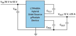
For a very compact solution, the LTM4654 is a complete hybrid-topology step-down DC-DC power module that belongs to the μModule family from Analog Devices. The solution, the power MOSFETs, the switching controller IC, and the other major building blocks of a bus converter, can step down DC-link voltages as high as 55 V to lower, adjustable voltages of, for instance, 5 or 12 V. The converted power can be up to 300 W continuously.
The power inductor resides on the top of the package so that heat can be dissipated up-and-out of the power module and away from the circuit board. Only flying (charge pump) capacitors, bulk input and output bypass capacitors, and several other passive components for configurations are needed. Figure 3 shows a solution with the highly integrated LTM4654. It requires very few external components and allows for a conversion efficiency of 96.7% at a conversion of 48-V input voltage to 9-V output voltage at a 15-A load current.
In addition to pure voltage conversion, the module can be used both as a current source and as a current sink. This output source/sink switching mode means that bidirectional operation can take place to work with energy efficiently in a system. The LTM4654 could also be utilized in the negative voltage range to convert, for example, +30 V down to –7 V. This conversion occurs much like a buck regulator in the inverting buck-boost mode.
Furthermore, it’s possible to operate several of these hybrid converters in parallel. With two converters, twice the current and thus twice the power can be converted.
The “Hybrid” Future of High-Efficiency Non-Isolated Bus Converters?
For efficient voltage conversion, the usual circuit topologies, such as buck converter or various transformer-based solutions, aren’t the only options. Innovative, new solutions such as hybrid converters offer important advantages. These create higher efficiency, especially in bus converters in a range of applications, and they require little space on a circuit board.
>>Download the PDF of this article
About the Author

Frederik Dostal
Power-Management Technical Expert
Frederik Dostal is a power-management expert with more than 20 years of experience in this industry. After his studies of microelectronics at the University of Erlangen, Germany, he joined National Semiconductor in 2001, where he worked as a field applications engineer, gaining a lot of experience in implementing power-management solutions in customer projects. During his time at National, he also spent four years in Phoenix, Arizona (USA), working on switch-mode power supplies as an applications engineer.
In 2009, he joined Analog Devices, where since then he held a variety of positions working for the product line and European technical support, and currently brings in his broad design and application knowledge as a power-management expert. Frederik works in the ADI office in Munich, Germany.
Also check out my:
Comment About the Article
To join the conversation, and become an exclusive member of Electronic Design, create an account today!

Leaders relevant to this article: